Counter-top scanner with bump protection mechanism and scan angle adjustment mechanism

a counter-top scanner and bump protection technology, applied in the field of laser scanning systems, can solve the problems of scanner dropping, bumping, and crashing of scanners, and many existing bar code scanner designs are inadequately equipped to deal with mechanical strains and stresses of day-to-day use, and achieve the effect of reducing the performance of scanners, and reducing the number of bumps

Inactive Publication Date: 2005-02-24
METROLOGIC INSTR
View PDF13 Cites 27 Cited by
  • Summary
  • Abstract
  • Description
  • Claims
  • Application Information

AI Technical Summary

Benefits of technology

[0058] In this manner, the invention provides a rugged bar code symbol reading system having an automatic hand-supportable scanning device which can be used at a point-of-sale (POS) station as either a portable hand-supported laser scanner, or as a stationary laser projection scanner. This configuration permits omnidirectional bar code scanning from a hands-free standing position on a countertop or work surface, as well as from a hand-supported position for scanning large, heavy, or bulky items without requiring the scanner operator to remove and / or replace a scanner in a stand.

Problems solved by technology

Many existing bar code scanner designs are inadequately equipped to deal with the mechanical strains and stresses of day-to-day use.
In many point-of-sale and factory environments, scanners are dropped, banged, and bumped.
Delicate optical components may be damaged or misaligned, causing the performance of the scanner to degrade over time.
Unfortunately, virtually all existing scanners are fabricated of high-impact polystyrene plastic, which provides only limited protection against mechanical shocks and bumps.
In addition to lacking mechanical ruggedness, bar code scanners suffer from other deficiencies.
Although these systems provide both hands-free as well as hands-on modes of operation, each of these systems suffers from a number of shortcomings.
In particular, the spatial extent of the scan pattern produced from these scanners frequently results in the inadvertent scanning of code symbols on products placed near the scanner during its hands-free mode of operation.
On the the other hand, in the hands-on mode of operation, it is virtually impossible to use these scanners to read bar code symbol menus provided in diverse application environments.
In each of these scanner designs, the scanner is tethered to its base unit by a power / signal cord, and the user is required to handle the scanner housing in an awkward manner in the hands-on mode of operation, resulting in strain and fatigue and thus a decrease in productivity.
In addition, the control structure provided in each of these hand-held projection scanners operates the scanner components in a manner which involves inefficient consumption of electrical power, and prevents diverse modes of automatic code symbol reading which would be desired in many portable scanning environments.
Hand-held scanners are not convenient to use in assembly-line applications where the user processes bar coded objects over an extended period of time, or where the user requires the use of both hands in order to manipulate objects.
In other applications, hand-held scanners are difficult to manipulate while simultaneously moving objects or performing other tasks at a point-of-sale terminal.
However, by their nature, stationary laser scanners render scanning large, heavy objects a difficult task, as such objects must be manually moved into or through the laser scan field.
While such scanners may be suitable for certain applications, the physical configuration of the optical components necessary to produce such complex omnidirectional patterns has resulted in scanner housings which are quite large and bulky.
In many applications, this is inconvenient, especially when there is limited counter space.
However, the base must be permanently secured to the countertop, which prevents the scanner from being lifted by hand to scan large or bulky items which do not fit on the countertop.
Unfortunately, the user must return the hand-supportable housing to the base unit after each scan, requiring a realignment of the handle and handle receiving portions.
This realignment process becomes tedious and annoying with repeated use.
Moreover, the base unit is large and cumbersome for use in many point-of-sale environments.
Whereas bar code symbol scanning systems of the type disclosed in U.S. Pat. No. 4,776,297 permit reading of printed bar code information using either a portable (hands-on), or stationary (hands-free) mode of operation, such systems suffers from several significant drawbacks.
If the scanner operator needs to move the bag into position, this is a two-handed job in itself, and the task of manipulating a trigger on the scanner during this positioning process is cumbersome and tedious at best.
However, the '002 patent does not disclose or suggest any technique for combining the scan head and lower housing into a single package that is conveniently hand-held, but that can also be used as a free-standing scanner.
Moreover, the design of the '002 housing is directed to a single-line scanning pattern and would not lend itself to production of an omnidirectional scanning pattern.
Unfortunately, both of these scanners require the user to remove the hand-held scanner from a stand for hand-supported scanning.

Method used


Image

  • Counter-top scanner with bump protection mechanism and scan angle adjustment mechanism
  • Counter-top scanner with bump protection mechanism and scan angle adjustment mechanism
  • Counter-top scanner with bump protection mechanism and scan angle adjustment mechanism

Examples


first embodiment

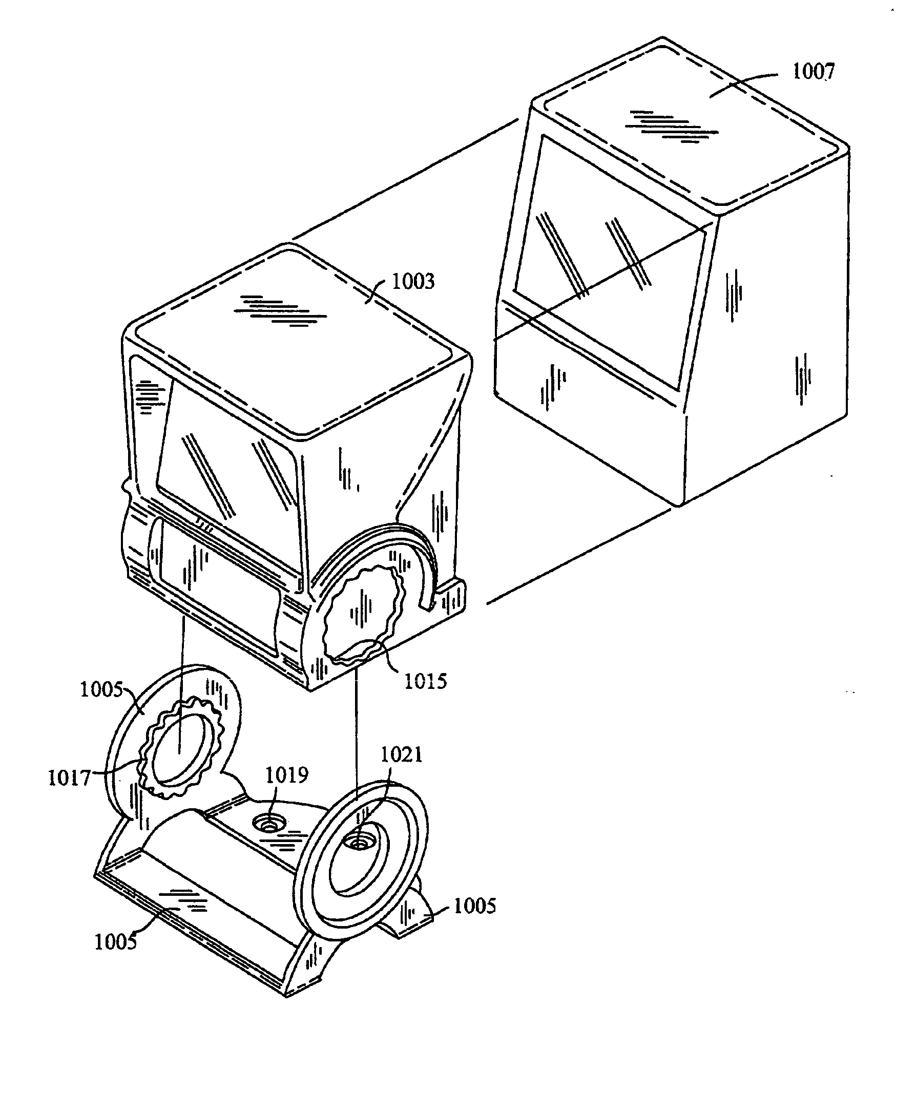
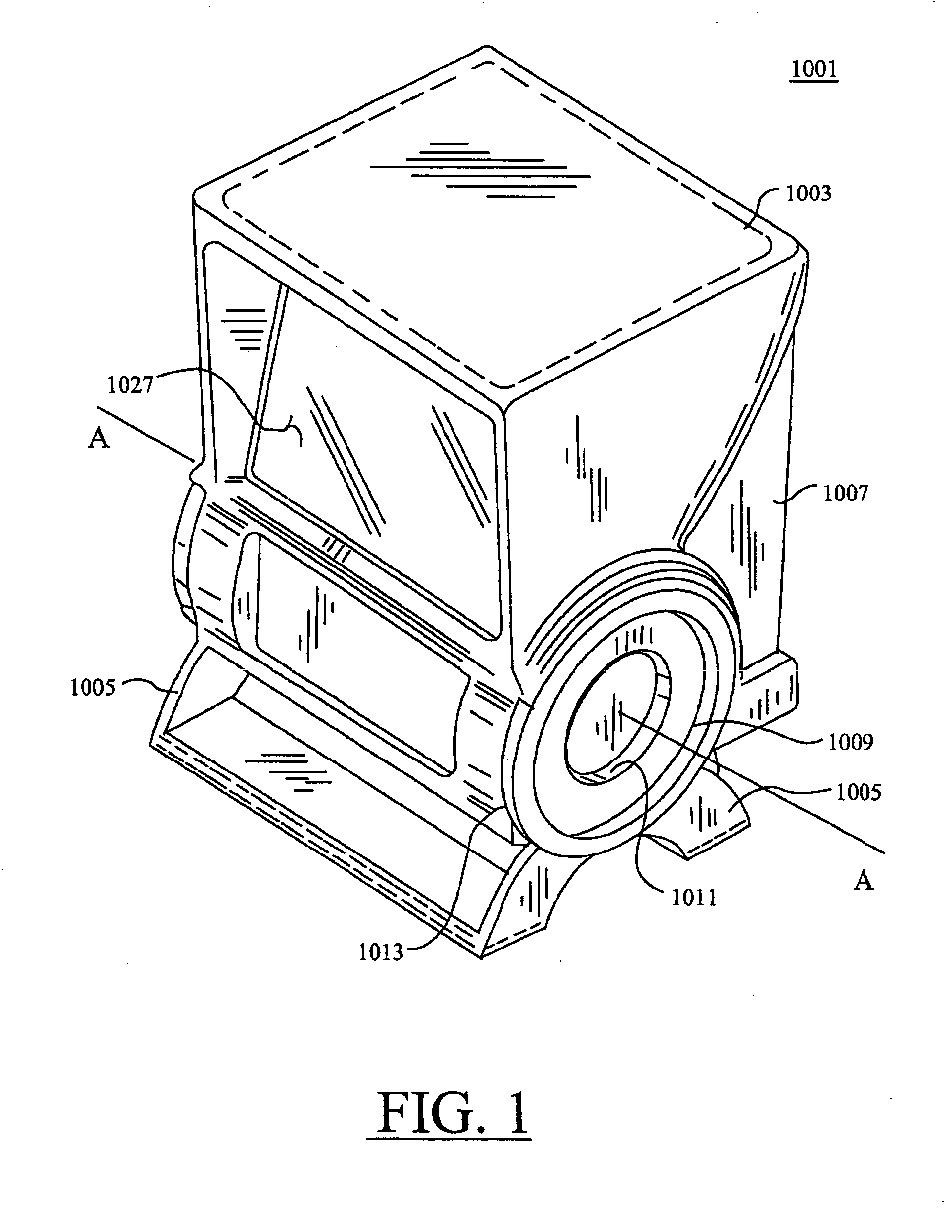
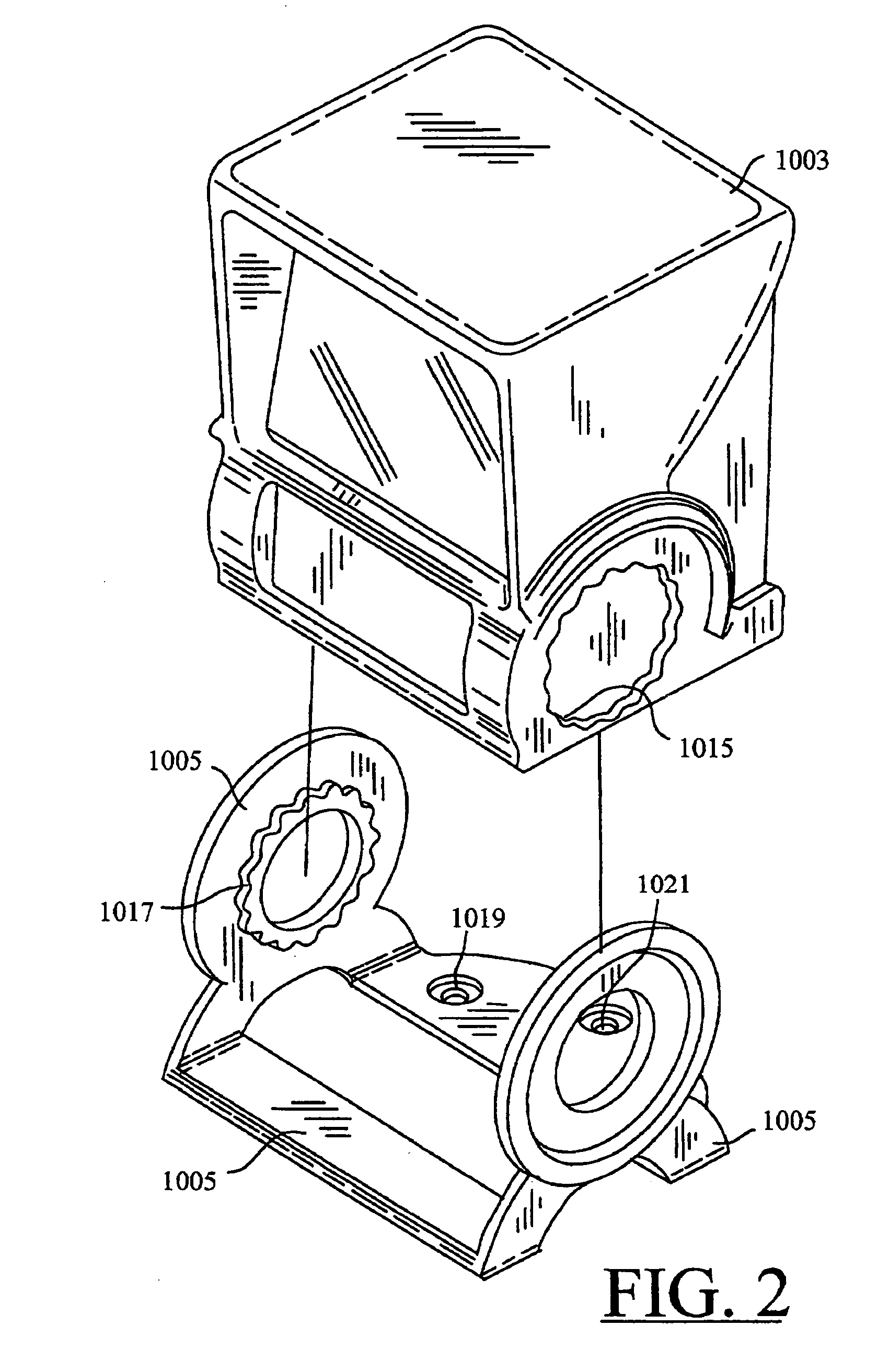
[0091]FIG. 1 is a perspective view of a multi-purpose bar code scanner 1001 that is hand-supportable, free-standing, and / or mountable, wherein the scanner is configured according to the invention. The scanner has a housing 1007 that is adjustably mounted to a movable bracket 1005, in the sense that bracket 1005 is movable relative to housing 1007. Accordingly, if movable bracket 1005 is mounted to a fixed surface such as a countertop, the movable bracket 1005 will remain fixed, but will permit adjustment of housing 1007 to any of a plurality of positions. One or more of these positions aim a window 1027 of housing 1007 towards the countertop surface and / or a point-of-sale area. Housing 1007 is equipped with a shock-absorbing mechanism in the form of protective sheath 1003. Protective sheath 1003 may be fabricated of rubber, flexible plastic, and / or any of various other materials capable of absorbing mechanical shock. Protective sheath 1003 may be fabricated so as to permit removal o...

second embodiment

[0097] Refer now to FIG. 5, which is a perspective view of a multi-purpose bar code scanner 10 that is hand-supportable, free-standing, and / or mountable. The scanner includes a housing that is configured according to the invention and has a substantially omnidirectional laser scanning platform mounted therein. Scanner 10 includes a scanning head 12 that is rotationally connected to a base unit 60. Scanning head 12 houses various associated optical components of the omnidirectional laser scanning platform as will be described in greater detail hereinafter.

[0098]FIGS. 5 through 8 set forth the general construction of the scanner housing. Scanning head 12 has an aperture 11 through which a substantially omnidirectional scanning pattern is projected. Scanning head 12 is formed in a generally spherical configuration with a flat front window 14 and top-mounted LED power and good read indicator 50. Head unit 12 is preferably molded of hard plastic or the like, and can be formed in two half...

third embodiment

[0141]FIG. 20, shows a third hardware embodiment for implementing an omnidirectional laser scanning platform mountable in the housing of the bar code scanners of FIG. 1 and / or FIG. 5. An automatically-activated bar code symbol scanning platform 100 pursuant to this third embodiment comprises a number of subsystems, namely: a laser-based bar code symbol detection subsystem 101; a laser-based bar code symbol reading subsystem 102; a data transmission subsystem 103; a state indication subsystem 104; a data transmission activation switch or control device 105A integrated with the scanner housing (not shown) in part or whole; a mode-selection sensor 105B integrated with the scanner housing in part or whole; and a system control subsystem 106 operably connected to the other subsystems described above. In general, the system 100 has a number of preprogrammed states of operation, namely: an object detection state; a bar code symbol detection state; a bar code symbol reading state; and a dat...


PUM


Abstract

An improved counter-top bar code scanner is equipped with a bump protection mechanism and a scan angle adjustment mechanism. The bump protection mechanism is provided in the form of a protective sheath fabricated of a shock-absorbing material. The scan angle adjustment mechanism is provided in the form of a movable bracket adjustably mounted to the scanner housing. If the bracket is mounted to a fixed surface, the bracket remains fixed but permits adjustments of the housing to any of the plurality of positions relative to the fixed surface.

Description

RELATED CASES [0001] This is a continuation of U.S. patent application Ser. No. 10 / 043,900, filed Jan. 11, 2002, which is hereby incorporated by reference.BACKGROUND OF THE INVENTION [0002] 1. Field of the Invention [0003] The present invention relates generally to laser scanning systems, and more particularly to countertop bar code scanners that are equipped with adjustable mounting mechanisms and adapted to operate in an automatic “hands-free” mode of operation. [0004] 2. Description of Background Art [0005] Optical scanners of various types have been developed for scanning and decoding bar code symbols. These scanners adapt readily to some operational environments, but present shortcomings when used in other situations. For example, consider system applications involving point-of-sale (POS) terminals in retail stores and supermarkets, inventory and document tracking, and diverse data control applications. Retail point-of-sale counters are prime sales areas Display designs and pro...

Claims


Application Information

Patent Timeline
Patent Type & Authority Applications(United States)
IPC IPC(8): G06K7/10
CPCG06K7/10881G06K7/10861
Inventor BYUN, SUNG HOSCHMIDT, MARK C.RUSSELL, GARRETT K.TRAVEA, FRANK J.
Owner METROLOGIC INSTR
Why Eureka
Try Eureka