Inflatable parachute for very low altitude jumping and method for delivering same to a person in need

Inactive Publication Date: 2005-02-24
SUHAMI AVRAHAM
View PDF14 Cites 35 Cited by
  • Summary
  • Abstract
  • Description
  • Claims
  • Application Information

AI Technical Summary

Benefits of technology

[0019] Any of the above described factors enables to increase the braking force of the parachute; their combination together with the elimination of the

Problems solved by technology

However the design of both inventions is such that very large amounts of helium are needed to make the parachute float, what makes them impractical.
We judge that the speed of gas actuated devices not to be suffic

Method used


Image

  • Inflatable parachute for very low altitude jumping and method for delivering same to a person in need
  • Inflatable parachute for very low altitude jumping and method for delivering same to a person in need
  • Inflatable parachute for very low altitude jumping and method for delivering same to a person in need

Examples


Embodiment Construction

[0033] As mentioned above, the main strategy employed in designing a parachute for low altitude jumping is to deploy the canopy before the jumper jumps into the air, thus allowing the canopy to exert its braking force immediately.

[0034] Table 1 shows the distance h1 traveled by the jumper and the resultant falling speed VC he attains by the end of the deployment time TC of a regular parachute. It shows the importance of reducing or eliminating the deployment time TC of the canopy, by pre-deploying it before the jump.

TABLE 1TC (seconds)h1 (meters)VC(meter / sec)0.51.24.914.99.8219.619.6

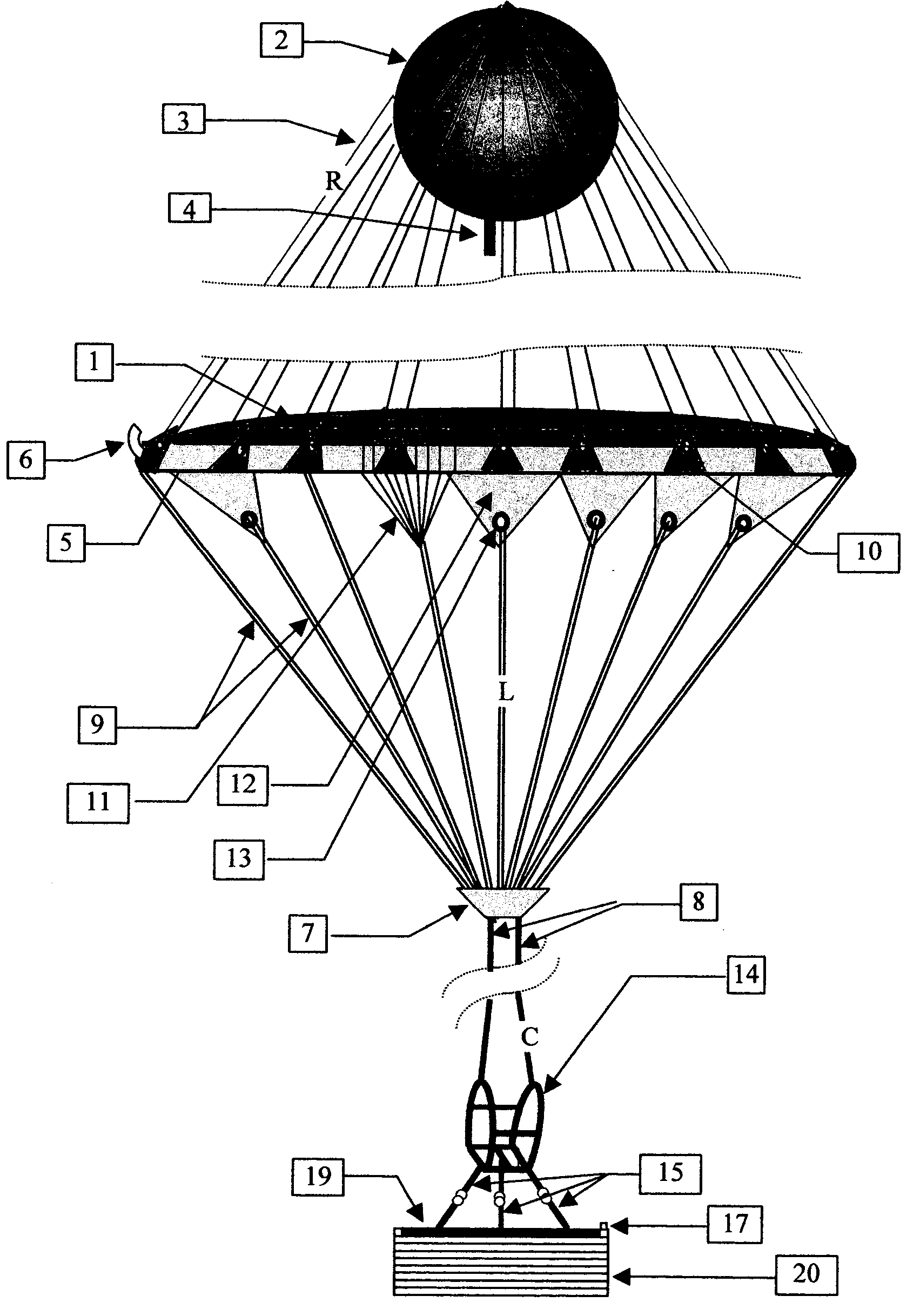
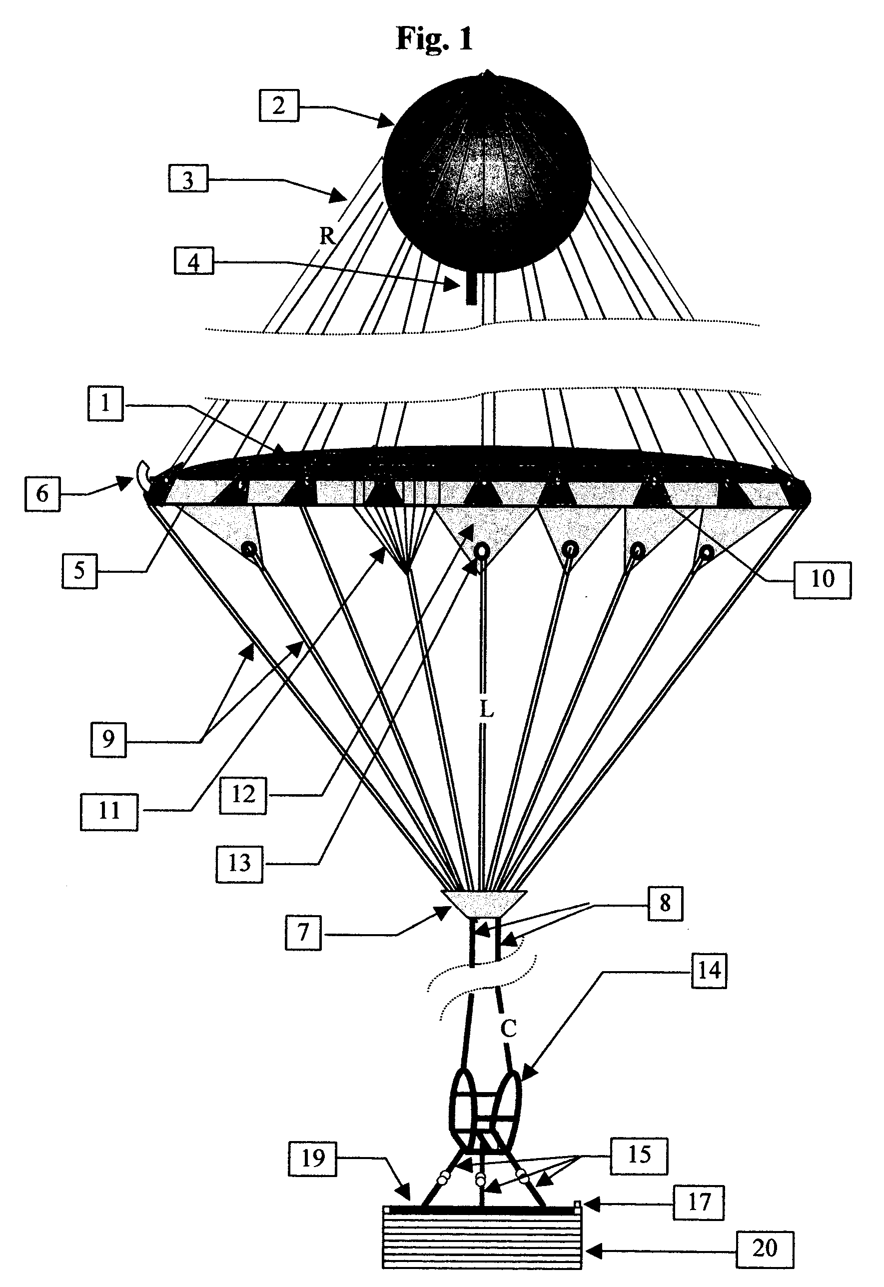
[0035] It has to be appreciated that a regular parachute has to develop a braking force, not only equal to the force of gravity exerted upon the jumper, but a much larger one, in order to decelerate the jumper that might have already reached a large falling velocity. This translates into a larger canopy and additional time for deceleration that limits the height from which it is safe to jump. FIG. 1 s...


PUM


Abstract

The invention consists in an inflatable ultralight parachute deployable before jumping, for jumping or releasing a load from any altitude, without experiencing unduly harm from the impact with the ground. It comprises at least one torus-shaped inflatable tube covered by a thin film substantially flat shroud whose buoyance lifts the parachute and when pulled down by the gravity of the attached body develops the braking force that decelerates its fall. The ultralight parachute is deployed either by the jumper if he has one, or by emergency helpers on the ground and subsequently lifted to the potential jumper. Optional accessories that enhance the braking force of the parachute and attenuate the impact of the attached body with the ground, include an aerodynamically shaped inversed skirt surrounding the torus-shaped tube, an electro-mechanical reel that upon activation shortest the distance between the jumper and the canopy and an air mattress that floats beneath the jumper's feet for reducing the impact of the fall when hitting the ground.

Description

BACKGROUND OF THE INVENTION [0001] Parachutes serve to brake the free fall of objects or people in the atmosphere and reduce the falling speed to a level that makes the impact with the ground tolerable and does not cause undue harm. Parachutes are usually made from light-weight air-tight Zero Porosity fabrics and when opened, form a dome-like shape that holds a mass of air underneath. This mass of air when pulled down by the object attached to the fabric by suspension lines, exerts a force proportional to the squared velocity V2 of the falling object and in opposite direction to the motion. The magnitude of this braking force is proportional to the surface (S) the downwards falling parachute presents to the stationary air within which it moves. During the initial free fall period, until such time that the canopy unfolds, the falling body accelerates and keeps increasing its velocity. After the canopy unfolds and is fully deployed, the parachute starts moving at the speed, the fallin...

Claims


Application Information

Patent Timeline
IPC IPC(8): B64D17/66B64D17/72B64D17/74B64D17/78
CPCB64D17/66B64D17/78B64D17/74B64D17/72
Inventor SUHAMI, AVRAHAM
Owner SUHAMI AVRAHAM
Why Eureka
Try Eureka