
Connecting structure for a thermoplastic tube, integrated assembly and method

a technology of connecting structure and thermoplastic tube, which is applied in the direction of hose connection, pipe-joint, coupling, etc., can solve the problems of inability to form a simple connecting structure, inconvenient use, and insufficient stress strength of the thick resin tube by itself to form a simple connection structure, etc., to achieve the effect of preventing disengagemen

Inactive Publication Date: 2005-02-24
SUMITOMO RIKO CO LTD
View PDF9 Cites 16 Cited by
  • Summary
  • Abstract
  • Description
  • Claims
  • Application Information

AI Technical Summary

Benefits of technology

[0013] The annular rubber band may be made of a vulcanized rubber or may be injection molded or extrusion molded utilizing a thermoplastic elastomer with good heat resistance and may be formed by slicing a section from a cylindrical tubular body of such composition. The annular rubber band does not contact the fluid inside the pipe. Further, the annular rubber band is fitted over the resin tube and configured to tighten around the open end of the resin tube when the tube connecting portion of a quick connector is inserted therein thereby preventing the resin tube from disintegration. The annular rubber band may have an inner diameter which is equal to or nearly equal to the outer diameter of the resin tube before the tube connecting portion of the quick connector is press fitted therein and should preferably be longer in length than the outer diameter of the connecting portion of the quick connector by about 2.0 mm or more. The annular rubber band thus tightens the resin tube when the tube connecting portion is inserted therein and increases the engaging force between the resin tube and the tube connecting portion. The stress or pressing force of the annular rubber band does not decrease at a high temperature and / or high pressure even though a fluid at high temperature flows through the resin tube and the tightening force does not mitigate at the connecting end of the resin tube. The connecting structure is adaptable to a resin tube having an inner diameter in a wide range of between 6.0-40 mm and a thickness of 0.5-4.0 mm.
[0018] Moreover, it is also desirable for the open end of the resin tube to be enlarged such that the inner diameter thereof becomes 5%-20% larger than the outer diameter of the tube connecting portion before or during press fitting to prevent any entrapment of the annular stopper within the resin tube.
[0020] To facilitate press fitting the tube connecting portion should have guiding tapered surface at the longitudinal end thereof. The guiding portion may have an outer diameter which is about equal to or somewhat larger than the inner diameter of the open connecting end of the resin tube. As a result, enlargement of the connecting end of the resin tube begins upon entry of the tapered surface. A large differential elasticity is thus generated on the resin tube at the border defined by the longitudinal end of the tube connecting portion. Any longitudinal vibration or displacement of the resin tube relative to the tube connecting portion causes shifting of the tube connecting portion to centralize stress. Abrasion may also result thereby wearing out the resin tube and the tube connecting portion. For this reason the longitudinal tip of the rubber band should be spaced apart from the longitudinal end of the tube connecting portion to prevent the tip of the tube connecting portion from being displaced upon entry into the resin tube. It is effective that the longitudinal tip of the rubber band be designed to contact or push the enlarged connecting end of the resin tube. In addition, the resin tube is thinned at the tip in the shaft direction, making the tip susceptible to damages or breakage. Therefore, it is a good idea that the longitudinal tip of the rubber band be positioned somewhat beyond the longitudinal tip of the tube connecting portion such that the resin tube is pushed against the tip or the tip portion of the rubber band in the shaft direction when the resin tube is displaced relative to the tube connecting portion. This prevents the tip of the tube connecting portion from displacement or centralization of stress. It is effective that the longitudinal tip of the rubber band be designed to contact or push the outer circumference of the resin tube being somewhat enlarged at a point more toward the outside the longitudinal tip of the tube connecting portion in the shaft direction.

Problems solved by technology

Nonetheless a rubber hose is too heavy and is not manageable for this application.
A thick resin tube by itself is not suitable to form a simple connecting structure for use with a quick connector since the only force fitting the resin tube to the tube connecting portion of a quick connector is the stress from the thick resin tube pushing against the tube connecting portion of the quick connector.
This stress is not strong enough to hold the resin tube against the force working to pull it out of the tube connecting portion during fluid delivery.
This will promote or generate creep at the resin tube's connecting end which cancels the tightening force at the connecting end causing the resin tube to fall off easily.
Further tightening of the resin tube at the end of the tube connecting portion does not help the resin tube and / or the tube connecting portion to resist the internal high pressure.
A tube composed of resin material is therefore not currently desirable for use in the plumbing of radiator and / or heating systems.
A resin tube would also provide an unreliable connection for use with a quick connector in these applications as well.
As a result, the over all edge of the resin tube does not bond well to the connector, causing the connector to break or crack at the edge of the resin tube.
For example, a resin tube, which is constructed with an outer layer made of heat resistant Nylon 12 (PA 12) and an inner layer made of water resistant polypropylene (PP), polyolefin, or fluororesin, has a drawback in that the inner layer does not completely bond to a connector made of Nylon 12 (PG 12 GF) containing glass fiber.
Therefore, many configurations of this type do not provide a reliable connecting structure for a resin tube.

Method used


Image

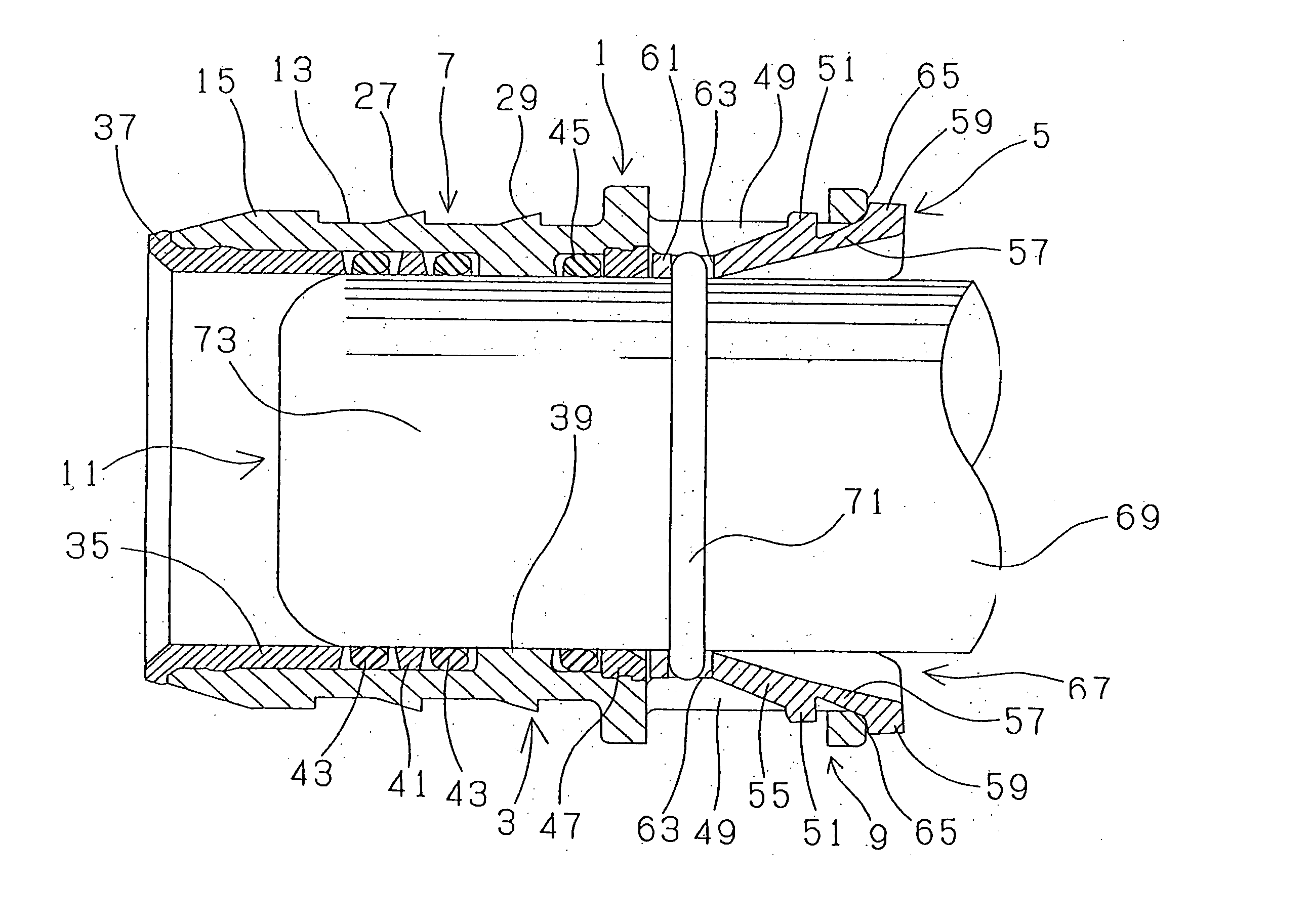
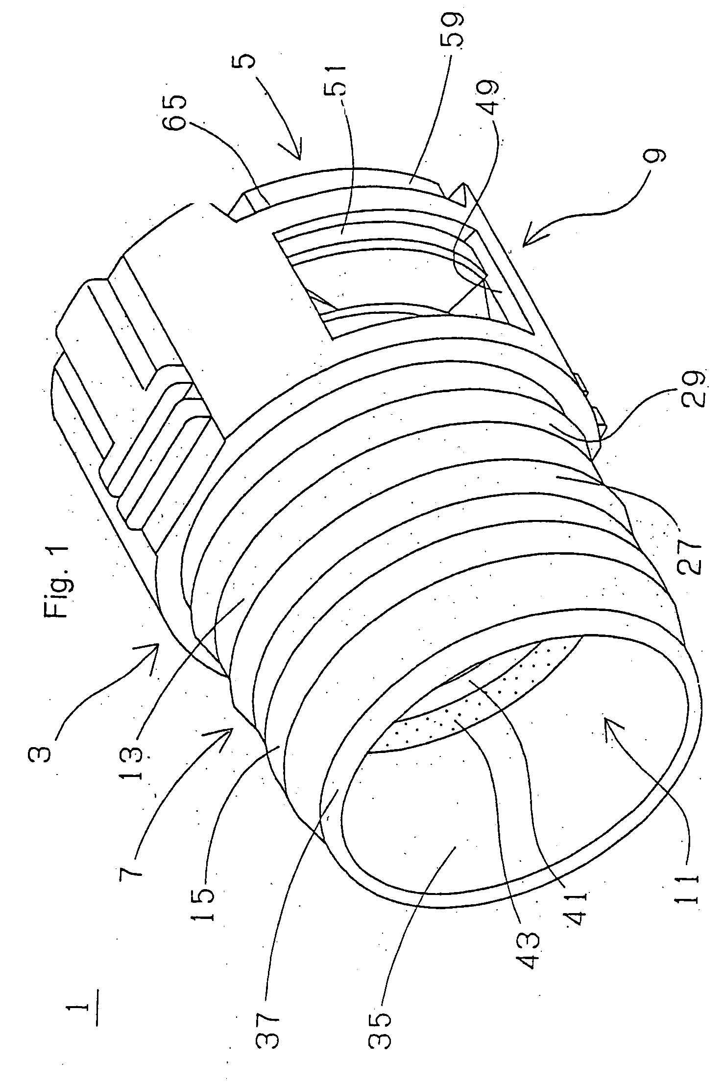
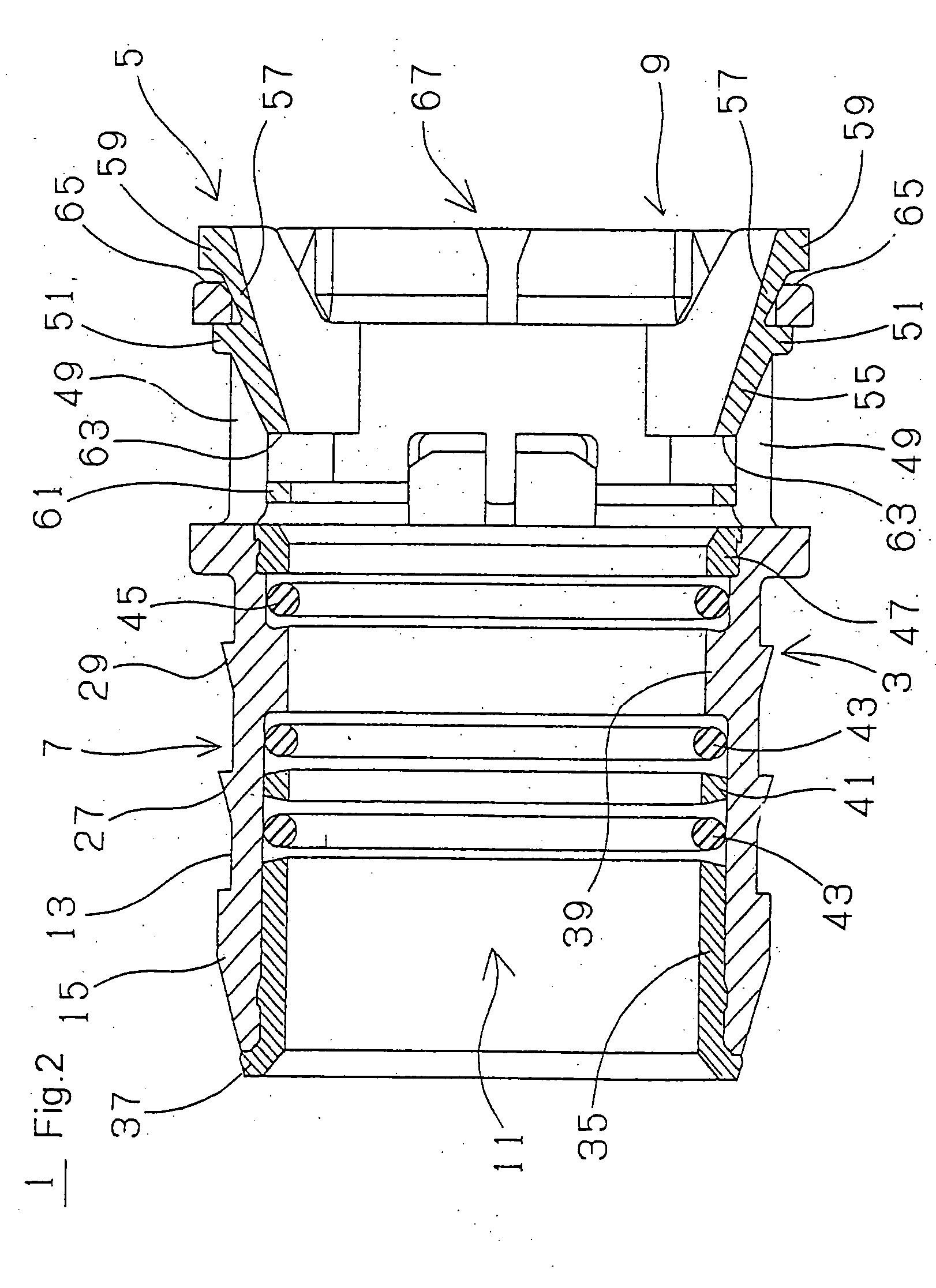
  • Connecting structure for a thermoplastic tube, integrated assembly and method
  • Connecting structure for a thermoplastic tube, integrated assembly and method
  • Connecting structure for a thermoplastic tube, integrated assembly and method

Examples


second embodiment

[0054] An annular channel 91 may be provided on the annular stopper 15 at the first end of tube connecting portion 7 and a FVMQ O-ring 93 may be fitted to annular channel 91 to seal the linkage between the stopper 15 and the resin tube 75 as illustrated in FIG. 8. Alternately, an FKMQ O-ring 93 may be used for the tube. FIG. 8 is a diagram illustrating a second embodiment for connecting quick connector 1 to resin tube 75 utilizing O-ring 93.

third embodiment

[0055] In place of rubber band 79, a rubber band 95 may be used having a single EPDM layer of hardness 7 Mohs which is 40 mm long with an inner diameter of 34.5 mm and a thickness of 5.0 mm. The rubber band 95 is fitted to the outer circumference of the connecting end 77 of resin tube 75 in the same manner as was rubber band 79. FIG. 9 is a diagram illustrating a third embodiment in which the quick connector 1 has the O-ring 93 placed around tube connecting portion 7 before being connected to resin tube 75 with rubber band 95. Alternately, the quick connector may be used without O-ring 93.

[0056] Alternately, the outer circumference of rubber band 79 or rubber band 95 may be tightened by a clamping means. FIG. 10 is a diagram illustrating an embodiment utilizing a clamping means, specifically the screw type metallic band 97 having a screw at a longitudinal mid point where stopper 27 is provided on the outer circumference of the rubber band 79. FIG. 11 employs a screw type metallic ba...


PUM

PropertyMeasurementUnit
Lengthaaaaaaaaaa
Diameteraaaaaaaaaa

Abstract

A connecting structure and method for affixing an open end of a tube composed from thermoplastic resin material(s) to a tube connecting portion of a quick connector having a cylindrical geometry and at least one annular stopper on the cylindrical outer circumference thereof with said tube connecting portion being adapted to be press fitted into said open end of said resin tube. The connecting structure comprises; an annular band composed of elastomeric rubber which surrounds the open end of said resin tube adjacent the location of attachment to said quick connector having a length at least equal to the diameter of the cylindrical outer circumference of the quick connector and a diameter such that a tightening force is applied to the resin tube upon press fitting said tube connecting portion into the open end of said resin tube to prevent disengagement therefrom. The connecting structure forms an integrated assembly with the tube connecting portion of the quick connector.

Description

TECHNICAL FIELD [0001] The present invention is a Continuation-In-Part of U.S. patent application Ser. No. 10 / 775,474 filed on Feb. 9, 2004 and relates to a connecting structure for connecting a thermoplastic tube to fluid tube connector, an integrated assembly and method for connecting a resin tube to a fluid tube connector to provide piping for transmitting fluids in an automobile, home water heating systems, or for general industrial purposes.BACKGROUND OF THE INVENTION [0002] Automotive fuel tubes, for example, use a rubber hose which is flexible and can be freely bent for connection to a quick connector without relative displacement. Nonetheless a rubber hose is too heavy and is not manageable for this application. It would be preferable to use a resin tube and to connect the resin tube to another tubular body utilizing a quick connector as the coupling joint for fluid delivery therethrough. A quick connector has a tube connecting portion with a cylindrical outer circumference ...

Claims


Application Information

Patent Timeline
IPC IPC(8): F16L33/30F16L37/098F16L47/22
CPCF16L33/30F16L47/22F16L37/0987
Inventor KATAYAMA, KAZUTAKATAKAYANAGI, AKIRA
Owner SUMITOMO RIKO CO LTD
Learn More