Method & apparatus for charging, discharging and protection of electronic battery cells

a technology for electronic batteries and charging devices, applied in the field of electronic circuitry, can solve the problems of increased complexity of external components, unsatisfactory solution of battery packs, and inability to charge, discharge and protect electronic batteries

Inactive Publication Date: 2005-02-24
NAIR RAJENDRAN
View PDF8 Cites 30 Cited by
  • Summary
  • Abstract
  • Description
  • Claims
  • Application Information

AI Technical Summary

Benefits of technology

The invention is a novel circuit configuration for battery cell management within battery packs, employing sense and control circuitry that enables the use of enhancement-mode devices with PN junctions as the control gate and minimizes external components required.
FIG. 1 illustrates a system-level embodiment of the invention. The circuit configuration and the components within are commonly referred to as a battery-pack. As can be seen, the switch S controlled by the monitor / controller IC (MCIC) interrupts the circuit path from the battery cell to the load devices. A capacitor C is the only additional component utilized for the dual purpose of maintaining the gate voltage at pin VG under normal operating conditions as well as to determine a delay before a ‘reset’ action that transitions the system from a protected (shut-off) mode to a stand-by mode in the event of a load device short circuit. The concept of a dual function for the capacitor minimizes the number of components required, and in conjunction with the use of an enhancement-mode JFET device, for example, enables a much smaller value of capacitance and facilitates total component integration.
Prior art implementations also include either an external precision resistor (for load current sense, a critical function of battery packs) or an internal, trimmed resistance for the same purpose, both of which add another pin to the MCIC, integrated circuit area within the MCIC and cost. The invention does not require this external or internal resistor because it is capable of reasonably accurate load current measurements through the switch S by means of the availability of the voltages at the three terminals of the switch device as well as information about the control input current to the PN junction gate of the switch device. Again, the use of an enhancement-mode device with a PN junction control input as the gating switch in the system leads to this advantage.

Problems solved by technology

In addition to the complexity and cost of such implementations, the reliability of the turn-off action by the MCIC in the event of a short circuit may also be dependent upon the external components used for the negative voltage capability.
The added complexity of and dependence upon external components is not a desirable solution for battery packs.

Method used


Image

  • Method & apparatus for charging, discharging and protection of electronic battery cells
  • Method & apparatus for charging, discharging and protection of electronic battery cells

Examples


Embodiment Construction

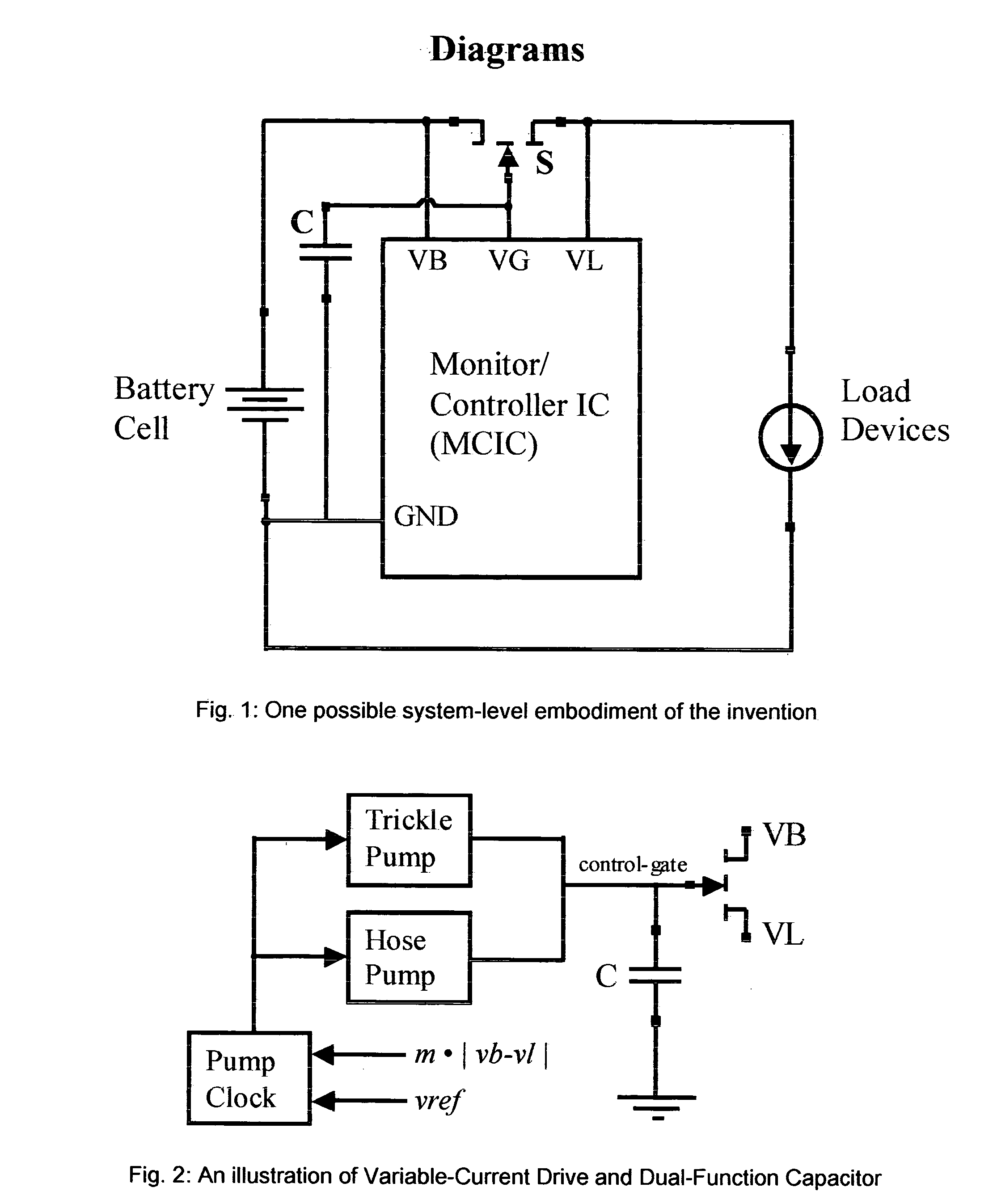
FIG. 1 shows key differences between the system embodiment and the prior art that include: 1. An enhancement-mode JFET employed as the switch device interrupting the battery cell circuit path within the battery pack, 2. The use of a capacitor connected to the control gate of the JFET switch device, 3. The elimination of a current measurement resistance in the batter cell circuit path, and 4. A Monitor / Controller integrated circuit (MCIC) with a reduced number of external pins.

Dual-Function Capacitor

A key concept within the architecture of the invention is the use of a single external (potentially integrated monolithically) capacitor for two important functions. The capacitor C in FIG. 1 is connected to the control gate of the switch device S with a value determined by operating parameters. The two functions of the capacitor are: 1. A filter / charge reservoir function for the output of the drive circuits connecting to the control gate of the switch device and 2. A delay eleme...


PUM


Abstract

A battery cell charge / discharge and protection circuit and system employing enhancement-mode junction-gated transistors as gating switches and minimizing external components is disclosed. The use of an enhancement-mode switch device with a PN junction control gate enables the elimination of external or internal precision resistors through the compensation of the voltage drop across the switch with the forward drop across the PN junction for temperature invariance of switch channel current estimation. The use of variable current drive circuits combined with a capacitor connected to the gate of the switch device facilitates energy consumption optimization while providing a timing mechanism for determining the recovery duration after a fault condition. Elimination of precision resistors and the minimization of the capacitance value facilitate a low-cost, single-chip battery protection solution.

Description

TECHNICAL FIELD OF THE INVENTION Embodiments of the invention relate to electronic circuitry commonly employed to protect and regulate the charging and discharging of electronic battery cells such as Lithium-Ion or Lithium-Polymer cells. Such circuitry falls under the broad category of power management electronics. BACKGROUND & PRIOR ART Many implementations for the regulated charging / discharging and protection of battery cells exist in the prior art. Most common among these is a circuit configuration employing a gating device, a monitor / controller IC and a few external components. The gating device is typically a series combination of two MOSFET devices inserted into the battery-cell current path. The external components are typically a precision resistor employed for current measurement and capacitor elements for supply decoupling, referencing and delay programming. The Monitor / Controller IC (MCIC) controls the gate inputs of the switch device to connect or disconnect the batter...

Claims


Application Information

Patent Timeline
Patent Type & Authority Applications(United States)
IPC IPC(8): H02J7/00H02M1/08
CPCH02J7/0031H02J7/0065H02J7/0091H02M1/08H02J2007/0039H02J2007/004H02J2007/0037H02J7/00304H02J7/00306H02J2207/20H02J7/00302H02J7/00309H02J7/007194
Inventor NAIR, RAJENDRAN
Owner NAIR RAJENDRAN
Why Eureka
Try Eureka