Multi-nozzle ink jet head

Inactive Publication Date: 2005-02-24
FUJIFILM HLDG CORP
View PDF2 Cites 2 Cited by
  • Summary
  • Abstract
  • Description
  • Claims
  • Application Information

AI Technical Summary

Benefits of technology

[0028] As a result, the ink chambers can be formed accurately using the metal mask, and moreover the strength of the ink chambers can be incre

Problems solved by technology

If electrical connection is carried out by providing contacts on top of or near to the piezoelectric bodies 111 as conventionally, then a problem of joining of neighboring contacts (shorting) may arise.
Moreover, when connecting a large number of points in a short time, the load on the piezoelectric bodies 111 becomes very high, and with thin-film piezoelectric bodies there is a risk of breakage, and hence connection

Method used


Image

  • Multi-nozzle ink jet head
  • Multi-nozzle ink jet head
  • Multi-nozzle ink jet head

Examples


first embodiment

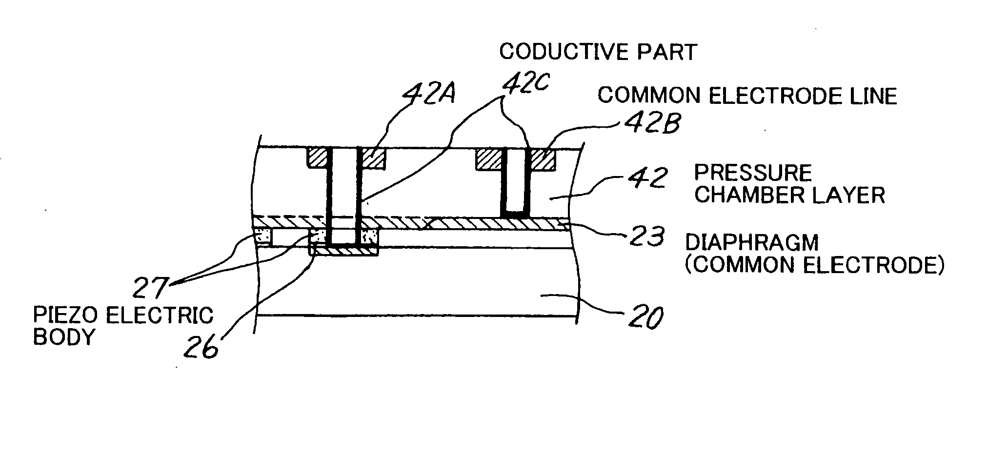
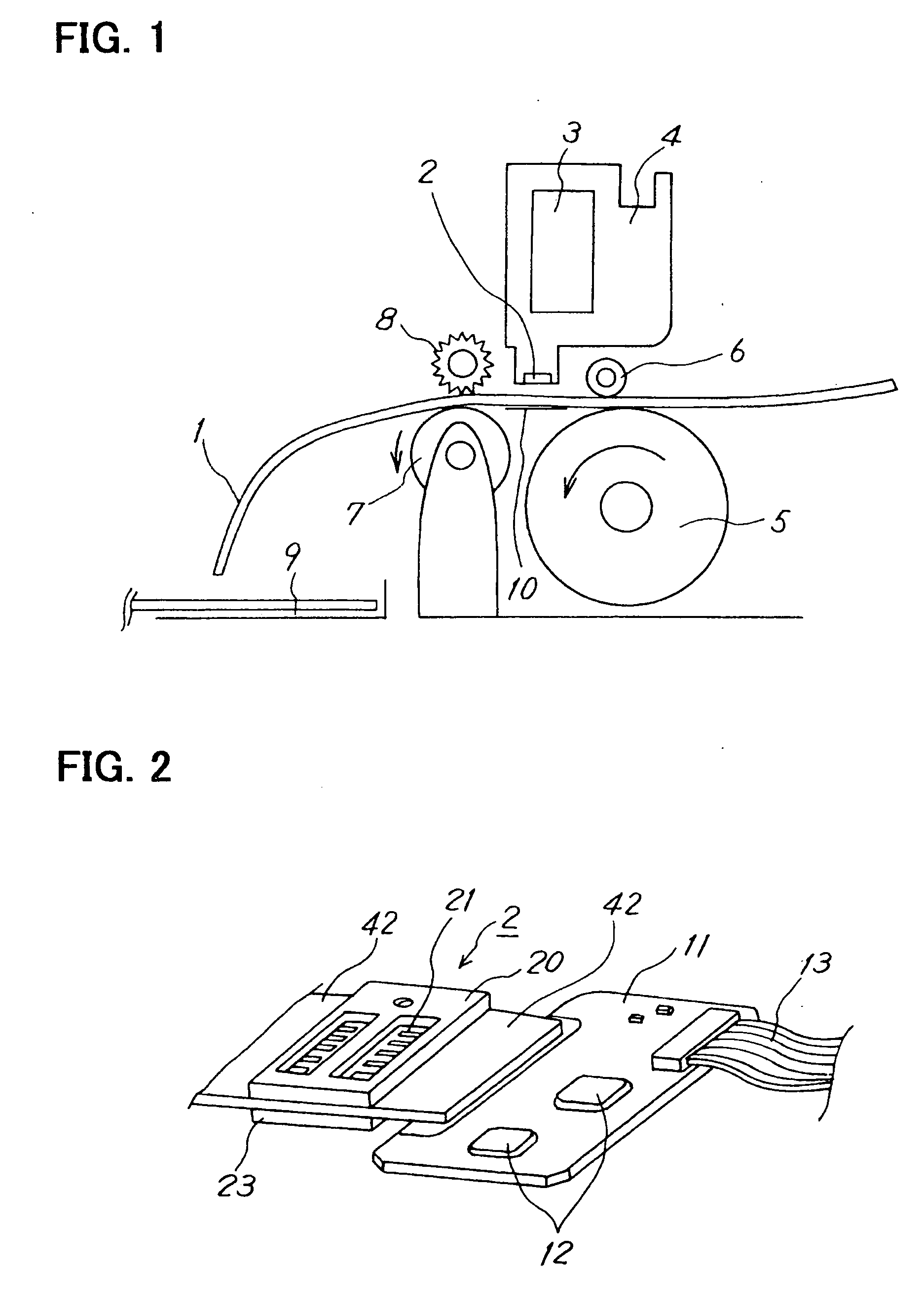
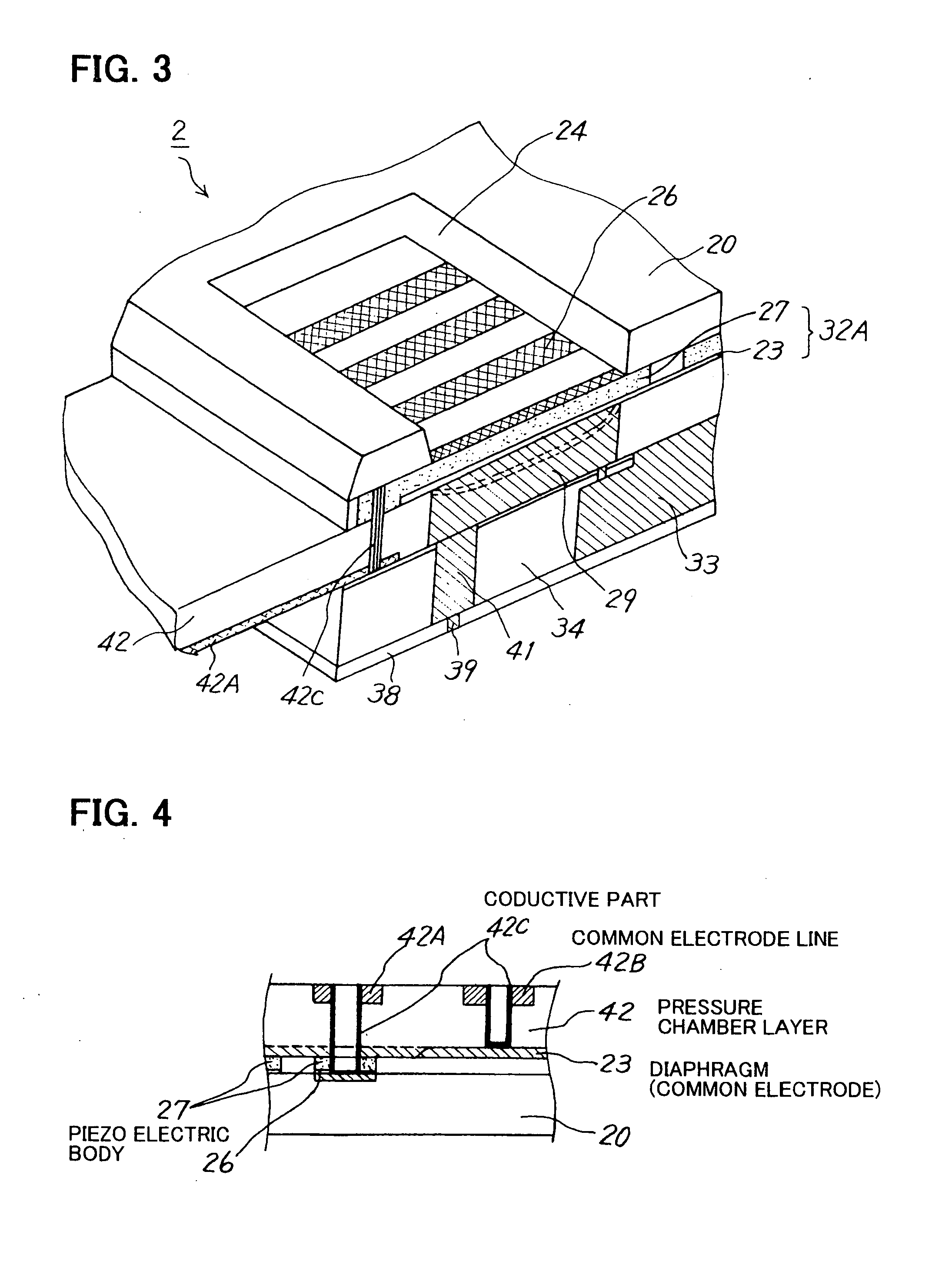
[0061]FIG. 3 is a sectioned perspective view of the ink jet head 2 of a first embodiment of the present invention, FIG. 4 is a sectional view of major parts of the head of FIG. 3, FIG. 5 is a drawing explaining the wiring patterns of the head of FIG. 3, FIGS. 7 and 8 are drawings for explaining the effects of the present invention, and FIGS. 9 to 12 consist of process diagrams for explaining a method of manufacturing the ink jet head of the first embodiment of the present invention.

[0062] As shown in FIG. 3, broadly speaking, the ink jet head 2 is constituted from a substrate 20, main body parts 42 and 34, a nozzle plate 38, ink ejection energy generating parts 32A and so on. As will be described later, the main body part 42 has a laminated structure including an insulating layer and wiring parts, and the main body part 42 also constitutes a pressure chamber forming part, with a plurality of pressure chambers (ink chambers) 29 being formed inside thereof. The main body part 34 has ...

second embodiment

[0095]FIG. 13 is a sectioned perspective view of the head of a second embodiment of the present invention, FIG. 14 is a sectional view of connecting parts in FIG. 13, FIG. 15 is an enlarged view of FIG. 14, FIG. 16 is a drawing for explaining the operation of the head, and FIGS. 17 and 18 consist of explanatory drawings of a manufacturing process of the head.

[0096] The present embodiment is an improvement of the head of FIG. 3, and elements the same as ones shown in FIG. 3 are represented by the same reference numerals. As shown in FIGS. 13 and 14, the wiring patterns 42A and 42B are formed on the front surface (substrate 20 side) of the pressure chamber forming member (FPC) 42. Moreover, a metal mask 44 for forming the pressure chambers 29 is provided on the FPC 42. This metal mask 44 fulfills a role of reinforcing the pressure chamber walls. Furthermore, metal layers 45 are plated onto the wall surfaces of the pressure chambers 29, thus electrically connecting the diaphragm 23 an...

third embodiment

[0103]FIG. 19 is a drawing of the constitution of the head of a third embodiment of the present invention; elements the same as ones shown in FIG. 2 and FIG. 6 are represented by the same reference numerals.

[0104] In this embodiment, driving circuits 12, connectors 71, and reinforcing plates 70 are provided on an FPC, which is the pressure chamber forming member 42 described above. As a result, because the driving circuits 12 are joined directly to the head itself, the contact process for the 25 wiring becomes unnecessary, and moreover the cost can be reduced. Moreover, when manufacturing the head, the state of each of the elements can be inspected using the circuits, and hence temporary connection for the inspection is not necessary, which is very effective for reducing the cost of inspection.

[0105] The present invention was described above through embodiments; however, various modifications are possible within the scope of the purport of the present invention, and these are not ...


PUM

PropertyMeasurementUnit
Currentaaaaaaaaaa
Digital informationaaaaaaaaaa
Electrical conductivityaaaaaaaaaa

Abstract

A multi-nozzle ink jet head formed by semiconductor processes is disclosed. The multi-nozzle head has a nozzle plate (38) in which are formed a plurality of nozzles (39), an FPC (42) in which are formed a plurality of ink chambers (29), and energy generating layers (23, 26, 27), and wiring patterns (42A, 42B) for the energy generating layers are provided on the FPC (42), thus making connection to external circuitry easy.

Description

TECHNICAL FIELD [0001] The present invention relates to a multi-nozzle ink jet head for applying pressure to pressure chambers and ejecting ink drops from nozzles and a manufacturing method thereof, and in particular to a multi-nozzle ink jet head for which the leading out of electrodes from a row of pressure energy generators is improved and a manufacturing method thereof. BACKGROUND ART [0002] An ink jet recording head has nozzles, ink chambers, an ink supply system, an ink tank, and transducers; by generating pressure in the ink chambers using the transducers, ink particles are ejected from the nozzles, and characters or images are recorded on a recording medium such as paper. [0003] For example, in well-known forms, the transducer is used a heat-generating element, or else a thin-plate-shaped piezoelectric element having the whole of one surface thereof bonded to the outer walls of an ink chamber. In the case that a piezoelectric element is used, a pulse-like voltage is applied ...

Claims


Application Information

Patent Timeline
IPC IPC(8): B41J2/05B41J2/14B41J2/16
CPCB41J2/14233B41J2/161B41J2/1623B41J2/1628Y10T29/49401B41J2/1646B41J2002/1425B41J2002/14491B41J2202/18B41J2/1643
Inventor KOIKE, SHUJISAKAMOTO, YOSHIAKISHINGAI, TOMOHISA
Owner FUJIFILM HLDG CORP
Why Eureka
Try Eureka