Francis turbine
a turbine and turbine blade technology, applied in the field of turbine blades, can solve problems such as loss of hydraulic efficiency, and achieve the effects of reducing secondary flow, improving blade shape, and reducing cavitation
- Summary
- Abstract
- Description
- Claims
- Application Information
AI Technical Summary
Benefits of technology
Problems solved by technology
Method used
Image
Examples
first embodiment
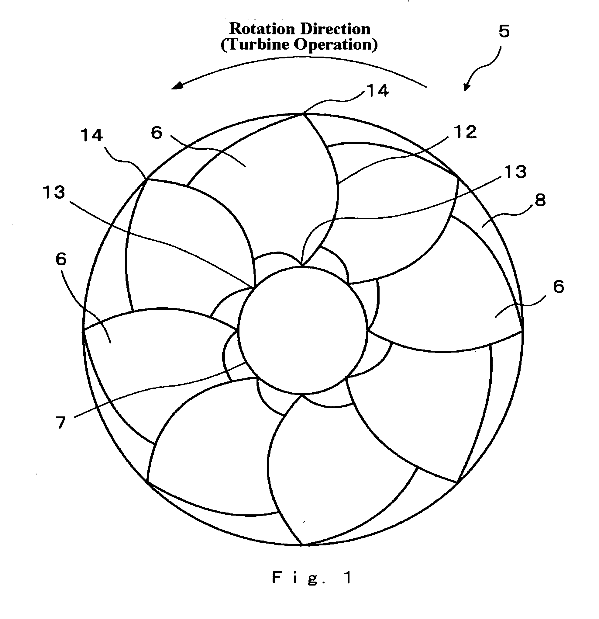
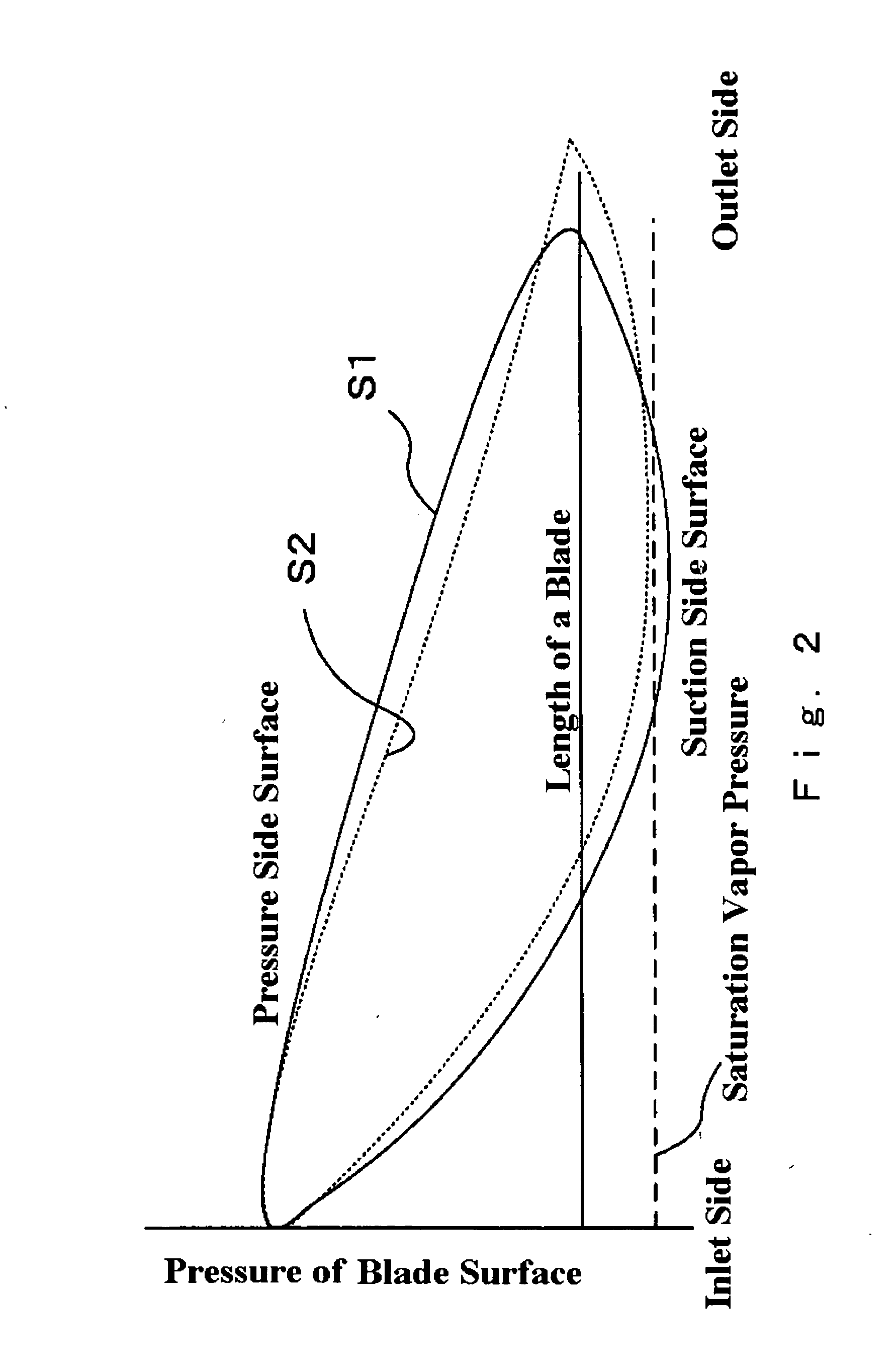
A first embodiment in accordance with the present invention will be explained with reference to FIGS. 1 to 4.
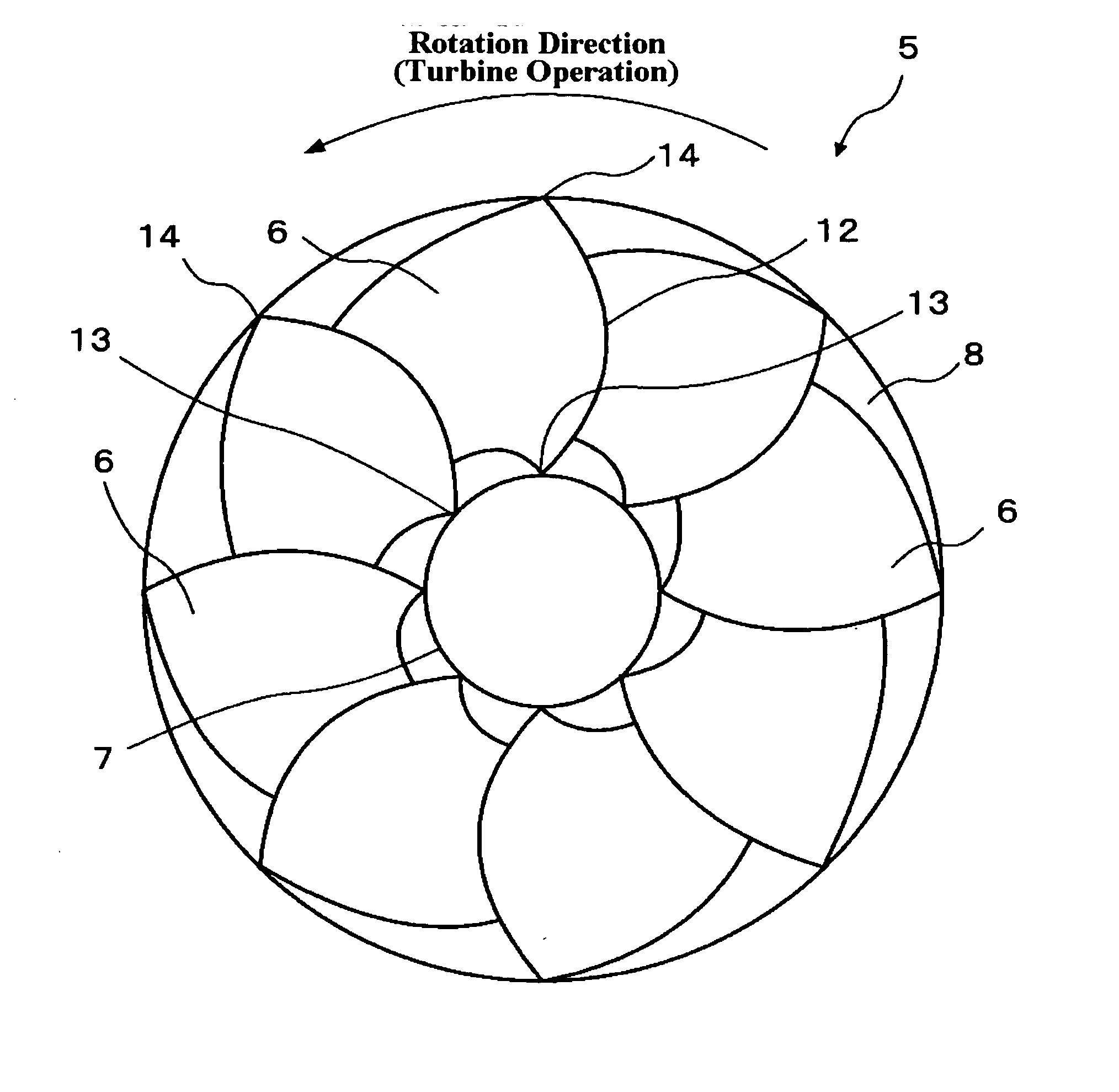
FIG. 1 is a plan view of a Francis turbine runner 5 seen from a runner outlet side, according to a first embodiment of the invention. In other words, FIG. 1 shows projected profiles of the outlet of the Francis turbine runner on a plane that is perpendicular to a rotation axis of the Francis turbine runner. A plurality of runner blades (runner vanes) 6 are disposed in a circumferential array on a crown 7. A head side of the runner blade 6 is supported by the crown 7 at a crown edge 13 (also referred to as a crown connecting point). A bottom side of the runner blade 6 is supported by a band 8 at a band edge 14 (also referred to as a band connecting point). FIG. 1 shows the Francis turbine runner 5 having eight runner blades 6 disposed therein. Thus, band 8 is coaxially coupled to crown 7 by blades 6 and a rotation shaft (not shown) is connected at the center of crown 7. Franci...
second embodiment
A second embodiment in accordance with the invention will be explained referring to FIGS. 5 to 9.
FIG. 5 is a plan view of the blades seen from an outlet side of the turbine (band side) with the band being removed from the runner. In FIG. 5, a symbol 20 indicates a Francis turbine runner. A symbol 21 indicates a blade, a symbol 22 indicates a crown. Same as first embodiment, Francis turbine runner 20 includes crown 22, a plurality of blades 21 and a band (not shown). A symbol 24 indicates a leading edge, which is an outer end of blade 21, in which water comes during the turbine operation. A symbol 31 indicates a trailing edge, which is an inner end of blade 21, where water flows out during the turbine operation. A symbol 28 indicates a rotating shaft (spindle) connected to crown 22. A rotation center of rotating shaft 28 is referred to as ◯ (also referred to as CL), which is corresponding to a rotation axis. Same as the first embodiment, FIG. 5 shows projected profiles of blades 21 o...
PUM
 Abstract
Description
Claims
Application Information
 - R&D
- Intellectual Property
- Life Sciences
- Materials
- Tech Scout
- Unparalleled Data Quality
- Higher Quality Content
- 60% Fewer Hallucinations
Browse by: Latest US Patents, China's latest patents, Technical Efficacy Thesaurus, Application Domain, Technology Topic, Popular Technical Reports.
© 2025 PatSnap. All rights reserved.Legal|Privacy policy|Modern Slavery Act Transparency Statement|Sitemap|About US| Contact US: help@patsnap.com


