Devices and methods used for shoulder replacement

Inactive Publication Date: 2005-02-24
CHUDIK STEVEN C
View PDF14 Cites 212 Cited by
  • Summary
  • Abstract
  • Description
  • Claims
  • Application Information

AI Technical Summary

Benefits of technology

[0017] Another aspect of the present invention provides a glenoid implant. The glenoid implant includes an ingrowth shell, a wear-resistant surface that is removably attached to the ingrowth shell. An advantage is that the ingrowth shell provides novel geometry and superior fixation to

Problems solved by technology

It requires an extensive exposure that irreversibly damages the rotator cuff and still fails to gain sufficient joint access to properly restore the native anatomic relationships of both the humeral head and glenoid surfaces.
Also, there remain issues with glenoid implant fixation and early loosening.
This can cause excessive traction on the arm which has resulted in injury to the nerves of the brachial plexus (Lynch N M, Cofield R H, Silbert P L, et al.
Additionally, despite the extensive exposure, conventional methods for shoulder replacement surgery still fail to properly restore the native anatomic relationships of the joint surfaces of the shoulder.
This poses great difficulty for the surgeon since the intramedullary axis has an inconsistent relationship to the humeral surface.
The humeral joint surface also possesses a complex anatomy with significant variability which cannot be entirely restored with conventional methods and implants.
The failure to restore the native anatomic relationships and biomechanics to the shoulder joint has proven to result in a significantly lesser functional and durable outcome (Williams G R, et al.
Conventional methods of shoulder replacement surgery also have difficulty gaining access to the glenoid

Method used


Image

  • Devices and methods used for shoulder replacement
  • Devices and methods used for shoulder replacement
  • Devices and methods used for shoulder replacement

Examples


example b

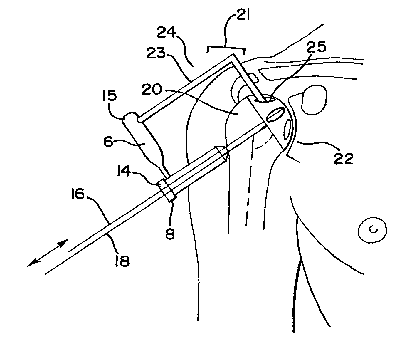
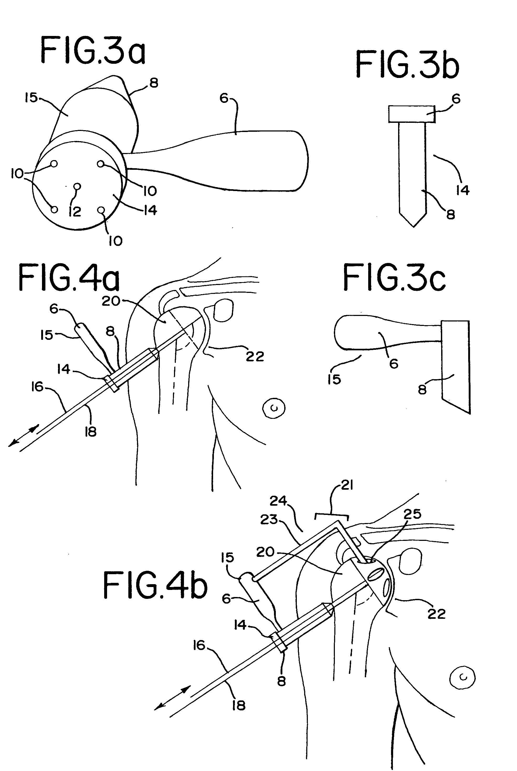
[0158] Example B includes a similar humeral surface 96 component and a cemented transhumeral stem 98 (FIGS. 17a-c). Again, the humeral surface component 96 is inserted through the anterosuperior passage, is either cemented or press-fit onto the prepared humeral surface 20 and impacted on the prepared humeral surface 20 against the glenoid 22. Another transhumeral stem 98 which possesses the male end of a morse taper is inserted into the female end on the non-articular side of the humeral surface component 96 and impacted against the glenoid. This stem 98 may be press-fit or cemented to the bony transhumeral portal. An endcap 106 is threaded into the non-articular side of the stem 98 to assist with later removal of the humeral surface implant 94. To fix with cement, a cementation catheter 84 is assembled to an opening in the endcap 106 and cement is injected through the cannulated transhumeral stem 98 exiting holes 99 at its articular end. The cement is injected until it becomes visi...

example c

[0159] Example C includes a similar humeral surface 96 component and an inflatable transhumeral stem 98 (FIGS. 19a-b) similar to technology used in the FIXION™ IM Nail (See “A New Expandable Implant for the Repair of Long Bone Fractures”, Sinha, Anjoy M. D. et al, published in www.Healthfocus.com). Again, the humeral surface component 96 is inserted through the anterosuperior passage and either cemented or press-fit, and further impacted on the prepared humeral surface 20 against the glenoid 22. Another transhumeral stem 98 which possesses the male end of a morse taper is inserted into the female end on the non-articular side of the humeral surface 96 component and impacted against the glenoid 22. The inflatable stem 98 is an expandable tube that is reinforced with longitudinal bars and has a one-way valve system on the end that doesn't mate with the humeral surface component. Once positioned, the stem 98 is inflated or expanded from its collapsed position with a specialized saline ...


PUM


Abstract

The present invention provides a method and devices for shoulder replacement surgery that spares the rotator cuff. The method utilizes two anterosuperior passages to gain access to the glenohumeral joint, neither of which requires transaction of the rotator cuff. In addition a transhumeral portal created through the second anterosuperior passage for use as a working tunnel. Specialized instruments and implants are provided to work through both the anterosuperior passage as well as the transhumeral portal.

Description

[0001] Applicant claims, under 35 U.S.C §119(e), the benefit of priority of: 1) the filing date of Aug. 11, 2003 of U.S. Provisional Application No. 60 / 494,289, 2) the filing date of Oct. 8, 2003 of U.S. Provisional Application No. 60 / 509,655, 3) the filing date of Oct. 16, 2003 of U.S. Provisional Application No. 60 / 511,805, 4) the filing date of Nov. 19, 2003 of U.S. Provisional Application No. 60 / 523,401, 5) the filing date of Jun. 15, 2004 of U.S. Provisional Application No. 60 / 579,893 and 6) the filing date of Jul. 2, 2004 of U.S. Provisional Application No. 60 / 585,033, the entire contents of each of which are incorporated herein by reference.BACKGROUND OF THE INVENTION [0002] 1. Field of the Invention [0003] The present invention relates to methods, instrumentation, and implants for orthopaedic surgery and, more specifically, to rotator cuff sparing procedures and associated devices for shoulder replacement surgery. [0004] 2. Discussion of Related Art [0005] Orthopaedic surgeo...

Claims


Application Information

Patent Timeline
IPC IPC(8): A61BA61B17/16A61B17/17A61B17/88A61B19/00A61F2/00A61F2/30A61F2/40A61F2/46
CPCA61B17/1604A61B2017/1778A61B17/1617A61B17/1637A61B17/1684A61B17/1703A61B17/1721A61B17/1735A61B17/8875A61B2019/461A61B2019/481A61F2/30767A61F2/4003A61F2/4081A61F2/4612A61F2/4684A61F2002/30604A61F2002/30934A61F2002/4018A61F2002/4635A61F2310/00017A61F2310/00023A61F2310/00131A61F2310/00179A61B17/1606A61B17/1778A61B2090/061A61B2090/08021
Inventor CHUDIK, STEVEN C.
Owner CHUDIK STEVEN C
Why Eureka
Try Eureka