Friction stir welding apparatus and associated thermal management systems and methods

a technology of friction stir welding and welding equipment, which is applied in the direction of soldering equipment, manufacturing tools, auxillary welding devices, etc., can solve the problems of warping and other dimensional defects in the workpiece, poor quality and mechanical integrity of the weld joint, and the technique may create geometric distortions near the weld joint, etc., to achieve enhanced quality and mechanical integrity, improved fracture toughness, impact strength, fatigue properties

Active Publication Date: 2005-03-03
GENERAL ELECTRIC CO
View PDF10 Cites 71 Cited by
  • Summary
  • Abstract
  • Description
  • Claims
  • Application Information

AI Technical Summary

Benefits of technology

[0006] In various embodiments, the present invention provides thermal management systems and methods that allow a workpiece to be controllably heated during friction stir welding, such that the temperatures in the workpiece more closely match the temperatures in the pin tool. In this manner, the cooling rate of a weld joint may be controlled. This results in a weld joint of enhanced quality and mechanical integrity, free from defects and workpiece distortions and demonstrating improved fracture toughness, impact strength, and fatigue properties. This also allows for enhanced pin tool temperature control in the event that a consumable pin tool is used and minimizes problems associated with pin tool debris entrapment. Finally, pin tool wear is reduced and pin tool life increased.

Problems solved by technology

Likewise, other conventional joining techniques may create geometric distortions near a weld joint due to high temperature gradients induced in a workpiece during welding.
These geometric distortions may cause warping and other dimensional defects in the workpiece, as well as residual stresses that may cause premature failure by cracking in the heat-affected zone or weld joint, lamellar tearing, or by stress-corrosion cracking in some metals and metal alloys.
These relatively high temperatures in the pin tool, in combination with relatively low temperatures in the workpiece, may result in a weld joint of poor quality and mechanical integrity, prone to defects and workpiece distortions.
For example, solid-state welds, including inertia welds, translational friction welds, and the like, associated with titanium alloys, such as Ti 17 and the like, are typically characterized by poor fracture toughness and impact strength.

Method used


Image

  • Friction stir welding apparatus and associated thermal management systems and methods
  • Friction stir welding apparatus and associated thermal management systems and methods
  • Friction stir welding apparatus and associated thermal management systems and methods

Examples


Embodiment Construction

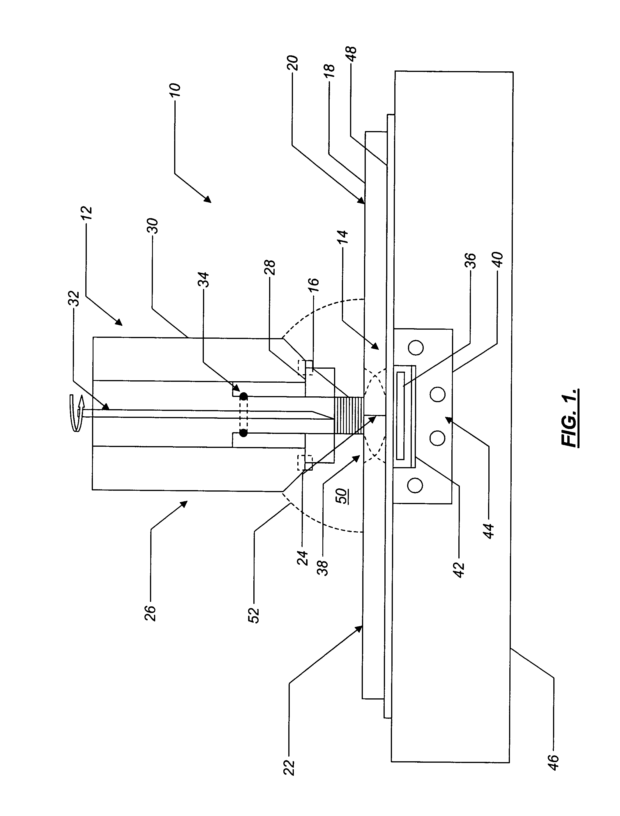
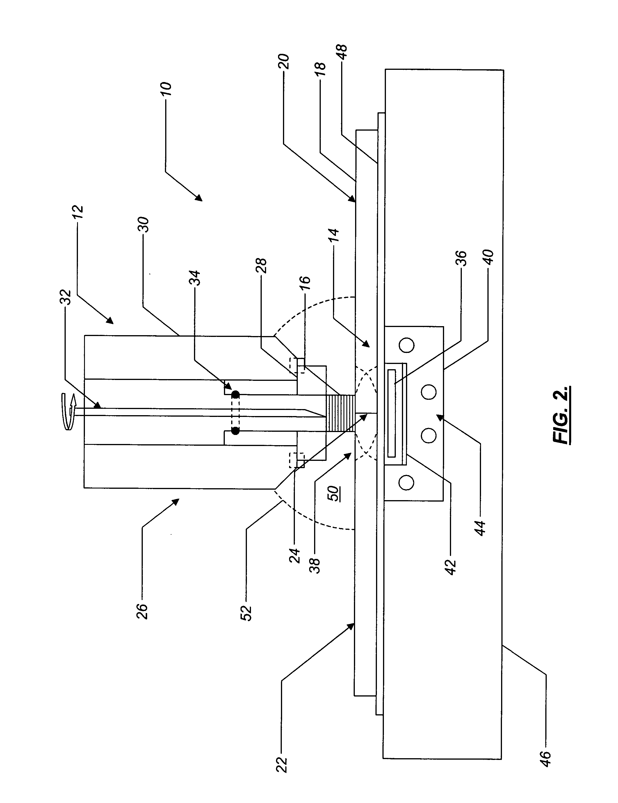
[0016] Referring to FIG. 1, in one embodiment of the present invention, a friction stir welding apparatus 10 includes a conventional or novel pin tool apparatus 12 and a thermal management system 14. Optionally, elements of the thermal management system 14 are incorporated into the pin tool apparatus 12. The pin tool apparatus 12 includes a rotating pin tool 16 that is selectively plunged into a rigidly clamped workpiece 18 consisting of two similar or dissimilar materials 20,22 disposed adjacent to one another and forming a joint 24 to be welded. The materials 20,22 include, for example, one or more metals, metal alloys (such as aluminum alloys, titanium alloys, nickel alloys, or the like), or other materials. In a typical application, the workpiece 18 has a thickness of between about 0.04 inches and about 1.5 inches, and the joint 24 to be welded has a length of between about 1 inch and about 300 inches or longer. Other thicknesses and lengths may, however, be used. For example, t...


PUM

PropertyMeasurementUnit
lengthaaaaaaaaaa
lengthaaaaaaaaaa
thicknessaaaaaaaaaa

Abstract

The present invention provides a friction stir welding apparatus and associated thermal management systems and methods for joining one or more similar or dissimilar materials forming a workpiece along a joint to be welded. The friction stir welding apparatus includes a pin tool apparatus selectively disposed adjacent to and in direct contact with a first surface of the workpiece along the joint to be welded and a heating member disposed adjacent to a second surface of the workpiece along the joint to be welded, the heating member operable for controllably heating at least a portion of the workpiece adjacent to the joint to be welded. The friction stir welding apparatus also includes an annular spindle having an interior portion and an axis, the interior portion of the annular spindle at least partially defining one or more cooling channels, the one or more cooling channels operable for containing a cooling fluid. The friction stir welding apparatus further includes a shoulder disposed adjacent to the annular spindle and substantially aligned with the axis of the annular spindle and a pin tool disposed adjacent to the shoulder and substantially aligned with the axis of the annular spindle. The cooling fluid is operable for cooling at least one of the shoulder and the pin tool.

Description

STATEMENT REGARDING FEDERALLY SPONSORED RESEARCH AND DEVELOPMENT [0001] The U.S. Government may have certain rights in the present invention pursuant to U.S. Air Force Contract No. F33615-99-2-5215.FIELD OF THE INVENTION [0002] The present invention relates generally to a friction stir welding apparatus. More specifically, the present invention relates to a friction stir welding apparatus and associated thermal management systems and methods. BACKGROUND OF THE INVENTION [0003] Friction stir welding is a solid-state joining technique that is well known to those of ordinary skill in the art. Typically, friction stir welding is used to join difficult-to-weld metals, metal alloys (such as aluminum alloys, titanium alloys, nickel alloys, and the like), and other materials. For example, certain aluminum alloys are sensitive in a plasticized heat-affected zone, where the base metal reaches temperatures between solidus and liquidus during welding. In this heat-affected zone, partial melting...

Claims


Application Information

Patent Timeline
Patent Type & Authority Applications(United States)
IPC IPC(8): B23K20/12
CPCB23K20/122B23K37/06B23K20/126B23K20/1235
Inventor SUBRAMANIAN, PAZHAYANNUR RAMANATHANHELDER, EARL CLAUDETRAPP, TIMOTHY JOSEPHHUNT, MARK LAWRENCESTOTLER, TIMOTHY V.
Owner GENERAL ELECTRIC CO
Why Eureka
Try Eureka