Liquid crystal display device with minimum ohmic contact between reflective and transparent electrodes

a liquid crystal display and transparent electrode technology, applied in optics, instruments, electrical equipment, etc., can solve the problems of large size and bulk of transmissive lcd devices, difficult for the crt to actively adapt to miniaturization and light weight, and high power consumption, and achieve the effect of simplifying process steps

Inactive Publication Date: 2005-03-03
LG DISPLAY CO LTD
View PDF3 Cites 2 Cited by
  • Summary
  • Abstract
  • Description
  • Claims
  • Application Information

AI Technical Summary

Benefits of technology

[0024] An object of the present invention is to provide an LCD device and a method for manufacturing the same that reduces an ohmic contact between a reflective electrode and a transparent electrode and simplifies process steps.

Problems solved by technology

However, it was difficult for the CRT to actively adapt to miniaturization and lightweight due to its weight and size.
However, the transmissive LCD device has large size and bulk, and high power consumption due to the back light.
However, there is a limitation that the reflective LCD device cannot be used in the dark outside.
However, the related art LCD device has the following problems.
That is, an ohmic contact is remarkably increased in this portion, and then a driving voltage is not uniformly provided to the ITO and the reflective electrode.
Accordingly, a parasitic capacitor is formed due to the insulating film formed between the reflective electrode and ITO, thereby resulting in a charged voltage negatively affecting the operation of pixels.

Method used


Image

  • Liquid crystal display device with minimum ohmic contact between reflective and transparent electrodes
  • Liquid crystal display device with minimum ohmic contact between reflective and transparent electrodes
  • Liquid crystal display device with minimum ohmic contact between reflective and transparent electrodes

Examples


first embodiment

[0042] First Embodiment

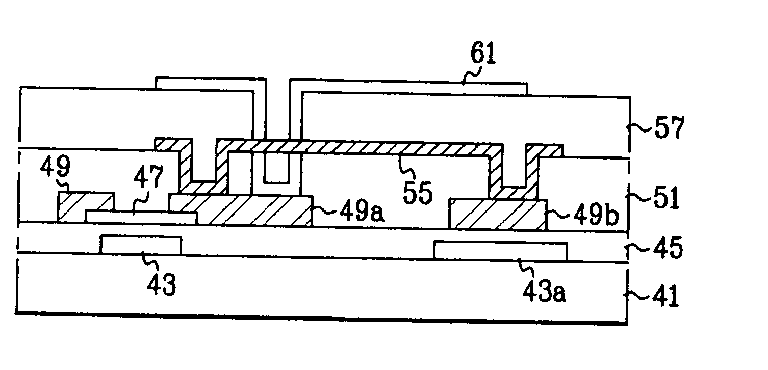
[0043]FIG. 4 is a sectional view showing the structure of an LCD device according to the first embodiment of the present invention. FIG. 5a to FIG. 5d are sectional views showing manufacturing process steps of the LCD device according to the first embodiment of the present invention.

[0044] For reference, FIG. 4 and FIG. 5a to FIG. 5d show a TFT region (I) and a storage region (II) simultaneously.

[0045] As shown in FIG. 4, a first substrate 41 is formed, and then a gate electrode 43 and a first electrode 43a of a storage capacitor are formed on the first substrate 41 to provide a certain distance between the two electrodes 43 and 43a. A first insulating film 45 is formed on the entire surface of the first substrate 41 including the gate electrode 43. Then, a semiconductor film 47 is formed on the first insulating film 45 above the gate electrode 43, and source / drain electrodes 49 and 49a are formed on the semiconductor film 47. A second electrode 49b of the s...

second embodiment

[0061] Second Embodiment

[0062]FIG. 6 is a sectional view of an LCD device according to a second embodiment of the present invention. FIG. 7a to FIG. 7d are sectional views showing manufacturing process steps of the LCD according to the second embodiment of the present invention, which show a TFT region (I) and a storage region (II) simultaneously.

[0063] As shown in FIG. 6, in the LCD device according to the second embodiment of the present invention, a first substrate 71 is formed, and then a gate electrode 73 and a first electrode 73a of a storage capacitor are formed on the first substrate 71 to prove a certain distance between the two electrodes 73 and 73a. A first insulating film 75 is formed on the entire surface of the first substrate 71 including the gate electrode 73 and the first electrode 73a. Then, a semiconductor film 77 is formed on the first insulating film 75 above the gate electrode 73, and source / drain electrodes 79 and 79a are formed on the semiconductor film 77. ...


PUM

PropertyMeasurementUnit
transparentaaaaaaaaaa
weightaaaaaaaaaa
sizeaaaaaaaaaa

Abstract

An LCD device and a method for manufacturing the same are disclosed, wherein it is possible to reduce an ohmic contact between a reflective electrode and a transparent electrode and to simplify process steps. In the LCD device having first and second substrates and a liquid crystal layer between the first and second substrates, the LCD device includes a gate electrode and a first electrode of a storage capacitor on the first substrate; a first insulating film on the entire surface of the first substrate including the gate electrode; a semiconductor film, source / drain electrodes and a second electrode of the storage capacitor on the first insulating film; a second insulating film on the first insulating film including the source / drain electrodes; a reflective electrode on the second insulating film to connect the drain electrode with the second electrode of the storage capacitor; and a transparent electrode connected with the drain electrode on a third insulating film formed on the second insulating film including the reflective electrode.

Description

RELATED APPLICATION [0001] The present application is a Rule 1.53(b) Divisional of application Ser. No. 09 / 962,444 filed Sep. 26, 2001, which claims the benefit of Korean Patent Application No. P2000-56618 filed Sep. 27, 2000, which is herein fully incorporated by reference.BACKGROUND OF THE INVENTION [0002] 1. Field of the Invention [0003] The present invention relates to a liquid crystal display device, and more particularly, to a method for manufacturing the same. [0004] 2. Background of the Related Art [0005] In general, a Cathode Ray Tube (CRT), one of display devices, has been widely used for monitors of information terminals and measuring instruments including a television. However, it was difficult for the CRT to actively adapt to miniaturization and lightweight due to its weight and size. [0006] A Liquid Crystal Display (LCD) device having a thin and small size has been actively developed in order to substitute for such a CRT. Recently, the LCD device is used as a flat pane...

Claims


Application Information

Patent Timeline
Patent Type & Authority Applications(United States)
IPC IPC(8): G02F1/1335G02F1/136G02F1/1362
CPCG02F1/133553G02F1/136227G02F1/136213G02F1/136
Inventor CHOO, KYO SEOP
Owner LG DISPLAY CO LTD
Why Eureka
Try Eureka