Data receiver and data transmission system

a data receiver and data transmission technology, applied in the field of data transmission systems, can solve problems such as reducing the reliability of data transmission, and achieve the effect of high-quality multi-level data transmission

Inactive Publication Date: 2005-03-03
PANASONIC CORP
View PDF6 Cites 10 Cited by
  • Summary
  • Abstract
  • Description
  • Claims
  • Application Information

AI Technical Summary

Benefits of technology

[0022] As described above, according to the present invention, highly accurate multilevel data transmission which

Problems solved by technology

In this situation, if noise or the like is applied to the system, determination of the receive signal level may becom

Method used


Image

  • Data receiver and data transmission system
  • Data receiver and data transmission system
  • Data receiver and data transmission system

Examples


first embodiment

[0034] (First Embodiment)

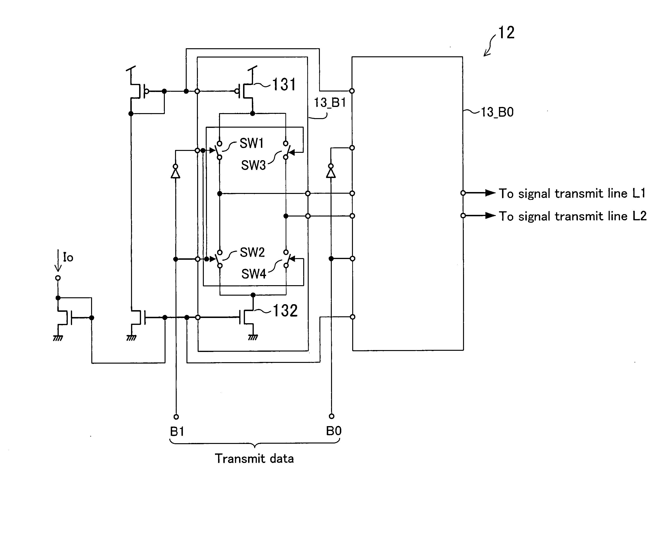
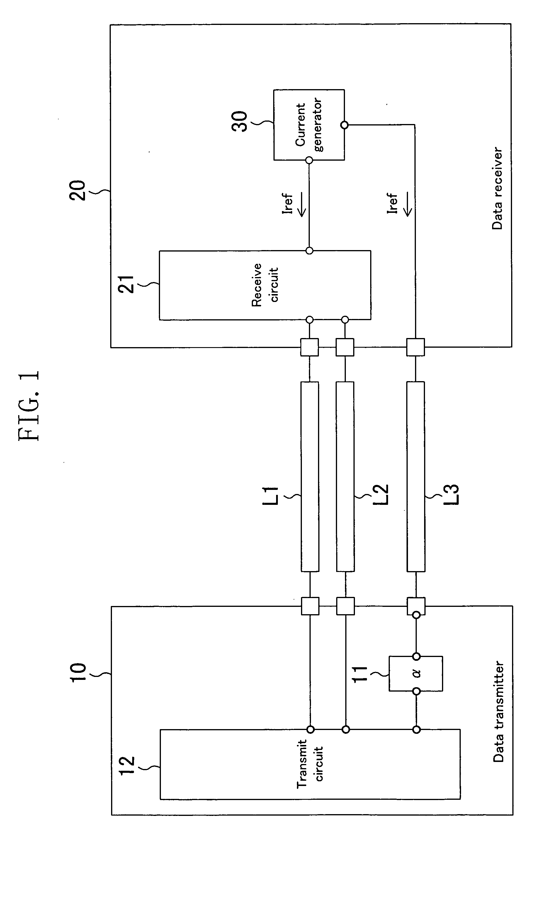
[0035]FIG. 1 illustrates the configuration of a data transmission system in accordance with a first embodiment of the present invention. The data transmission system of this embodiment includes a data transmitter 10 and a data receiver 20. The data transmitter 10 outputs via a signal transmit line L1 or L2 a current signal produced based on multilevel data and the data receiver 20 receives the multilevel data. Each of the data transmitter 10, and the data receiver 20 may be composed of a single chip LSI. The data transmission system of this embodiment further includes a current generator 30 for generating reference currents Iref. The current generator 30 is provided on the data receiver 20.

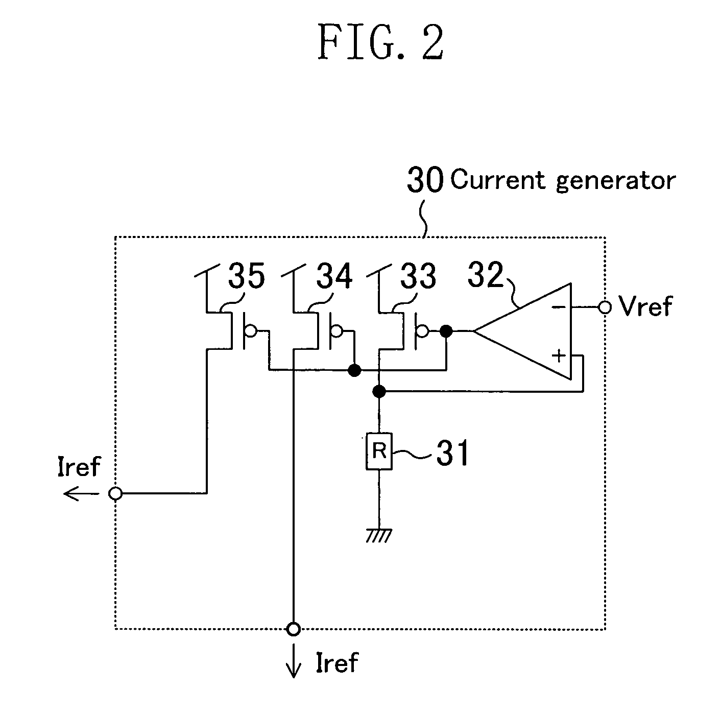
[0036]FIG. 2 illustrates the specific circuit configuration of the current generator 30. The current generator 30 receives a reference voltage Vref and outputs the reference currents Iref. In the current generator 30, one end of a resistance element 31 (resistance value R...

second embodiment

[0063] (Second Embodiment)

[0064]FIG. 7 illustrates the configuration of a data transmission system in accordance with a second embodiment of the present invention. The data transmission system of this embodiment differs from the data transmission system of the first embodiment in that a current generator 30 is provided not on a data receiver 20 but on a data transmitter 10. The components other than this are the same as those in the first embodiment, so the descriptions thereof will be omitted herein.

[0065] Even if the current generator 30 is formed on the data transmitter 10 as in this embodiment, effects similar to those of the first embodiment are attained. In other words, the current generator 30 may be provided anywhere in the data transmission system of this invention. The current generator 30 may be provided anywhere other than on the data transmitter 10 and the data receiver 20.

[0066] Although in the first and second embodiments, the data transmitter 10 and the data receiv...


PUM


Abstract

A data transmitter receives a reference current from a current generator and outputs as a current signal a current obtained by multiplying the reference current by a given number in accordance with the value of transmit data. A data receiver, on the other hand, receives the current signal from the data transmitter to generate a receive signal, while receiving a reference current from the current generator to generate a reference signal which is necessary for level determination of the receive signal. In this manner, the reference currents, from which the current signal and the reference signal are respectively generated, are supplied from the current generator that is used in common by the data transmitter and the data receiver.

Description

CROSS-REFERENCE TO RELATED APPLICATION [0001] This application is related to Japanese Patent Application No. 2003-304427 filed on Aug. 28, 2003, whose priority is claimed under 35 USC §119, the disclosure of which is incorporated herein by reference in its entirety. BACKGROUND OF THE INVENTION [0002] The present invention relates to data transmission systems, and more particularly relates to a technique for constructing data transmission systems for performing current-mode multilevel data transmission. [0003] Data transmission between LSIs has been conventionally performed in the following manner. FIG. 9 illustrates the configuration of a conventional data transmission system. An LSI 100, serving as a data transmitter, controls switches SW1, SW2, SW3 and SW4, as necessary, to electrically connect a current generator 101 or 102 to a signal transmit line L1 or L2 so as to output a current signal. On the other hand, an LSI 200, serving as a data receiver, passes the supplied current si...

Claims


Application Information

Patent Timeline
IPC IPC(8): H03K17/00H03K17/687H03K19/0175H04L25/02H04L25/06H04L25/49H04L27/00
CPCH04L25/062H04L25/49H04L27/00
Inventor DOSHO, SHIROTOKUNAGA, YUSUKE
Owner PANASONIC CORP
Why Eureka
Try Eureka