Miniature imaging encoder readhead using fiber optic receiver channels

a readhead and miniature technology, applied in the field of optical encoders including miniature readheads, can solve the problems of significant signal loss, limited conversion of high-frequency detector signals, and electrical readhead receivers (photodetectors), and achieve the effects of ultra-compact, high accuracy, and high speed

Inactive Publication Date: 2005-03-03
MITUTOYO CORP
View PDF14 Cites 21 Cited by
  • Summary
  • Abstract
  • Description
  • Claims
  • Application Information

AI Technical Summary

Benefits of technology

Hence, the invention overcomes the disadvantages of prior art optical displacement sensing devices and provides new application possibilities with a system that can provide measurements at extremely high speeds and that is ultra-compact, highly accurate, and economical.

Problems solved by technology

As previously outlined, electronic readhead receivers (photodetectors) such as disclosed in the '283 patent suffer limitations in converting the high frequency detector signals associated with high speed scale motion and transmitting those signals over long cables without significant signal loss or interference.

Method used


Image

  • Miniature imaging encoder readhead using fiber optic receiver channels
  • Miniature imaging encoder readhead using fiber optic receiver channels
  • Miniature imaging encoder readhead using fiber optic receiver channels

Examples


Embodiment Construction

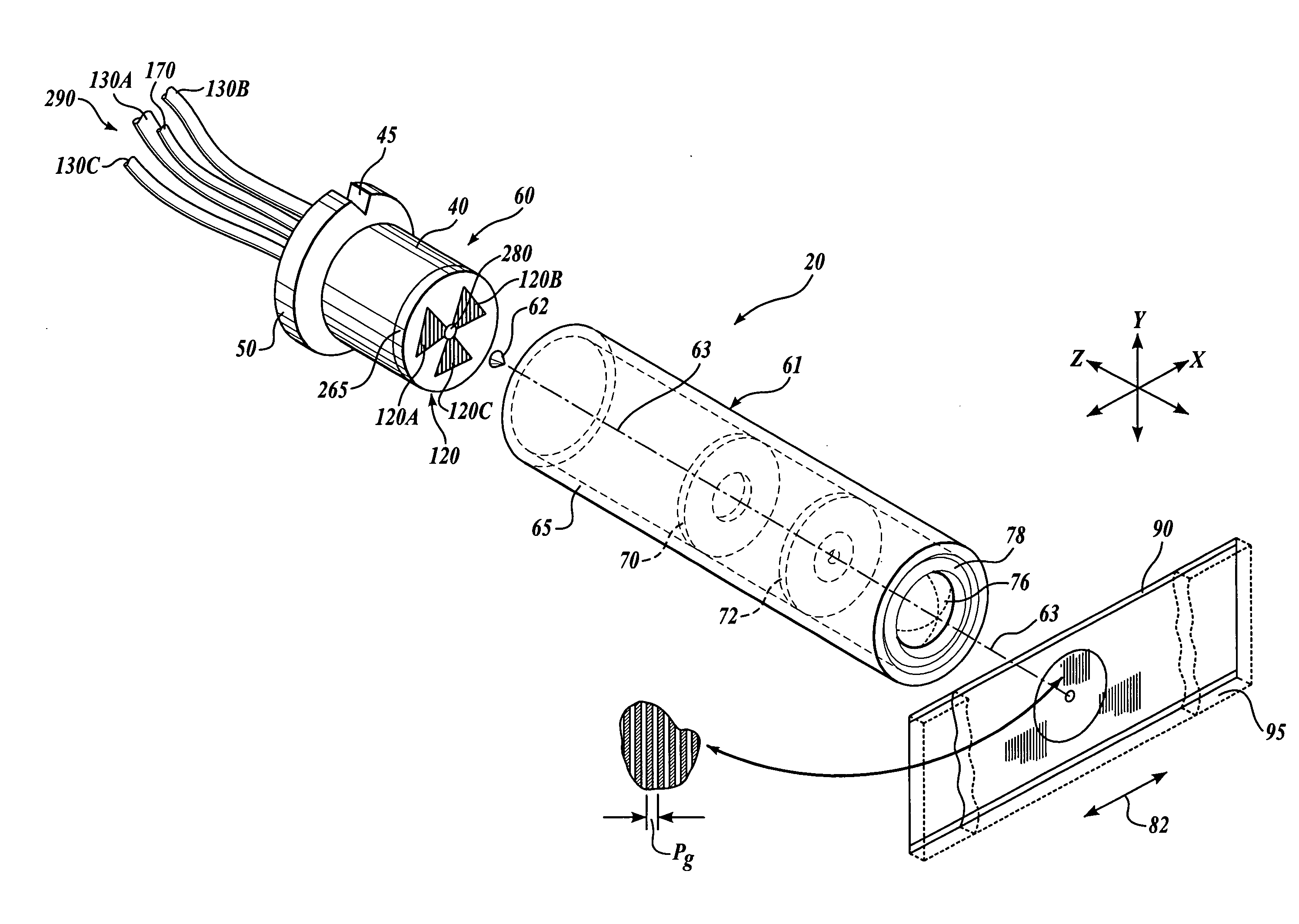
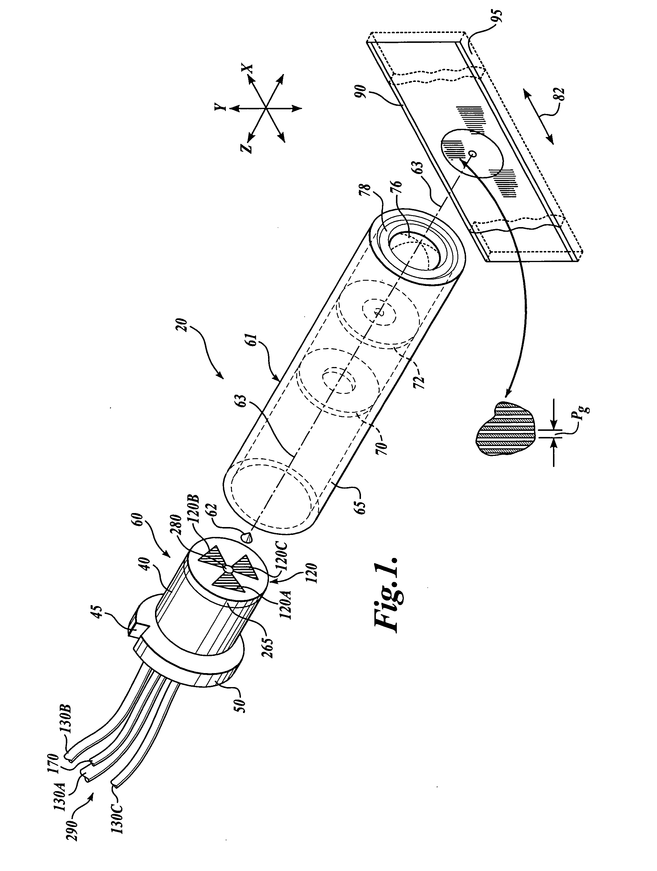
FIG. 1 shows a first generic embodiment of a fiber optic readhead arrangement 20 according to this invention. As will be described in more detail below, the fiber optic readhead arrangement 20 includes a readhead 60, an optical assembly 61, an axicon lens 62 and a scale 90. An imaging lens 76 within the optical assembly 61 is utilized to image the scale 90 onto the readhead 60. It should be understood that the scale 90 can extend to any desired dimension along the direction of the measuring axis 82. Thus, the scale 90 shown in the various figures herein can be interpreted as a segment of a much larger scale, in various exemplary embodiments according to this invention.

The readhead 60 is encased by a ferrule 40, which has a collar 50 and an alignment groove 45. The readhead 60 may be formed in accordance with the teachings of U.S. patent application Ser. No. 10 / 298,312, entitled “High Accuracy Miniature Grating Encoder Readhead Using Fiber Optic Receiver Channels,” filed Nov. 15, 20...


PUM


Abstract

A fiber optic readhead arrangement for imaging a scale onto a set of optical fiber receiver channels is disclosed. The readhead arrangement includes an imaging lens and may include an aperture positioned at a focal point of the imaging lens in a telecentric arrangement. An axicon lens may be utilized to direct source light away from the imaging lens and into a ring-shaped annular source lens which surrounds the imaging lens. A source lens may concentrate source light on the scale in an area where it will be imaged back through the imaging lens to the readhead. In one embodiment, multiple source fibers may be provided around the perimeter of the fiber optic readhead arrangement. In another embodiment, the receiver fibers may also function as source fibers. In various exemplary embodiments, high levels of displacement signal interpolation may be achieved to provide high resolution measurement.

Description

FIELD OF THE INVENTION This invention relates generally to displacement sensing optical encoders, and more particularly to an optical encoder including a miniature readhead that images a scale onto a set of optical fiber receiver channels in the readhead so as to provide an ultra-compact imaging encoder system. BACKGROUND OF THE INVENTION Various movement or position encoders for sensing linear, rotary or angular movement are currently available. These encoders are generally based on either optical systems, magnetic scales, inductive transducers, or capacitive transducers. Certain of these encoders are designed for making relative measurements. In such relative displacement or position encoders, measurements are typically made by sensing the relative change in position of the scales with respect to a reference position, which requires a sensing of the change in the scale pattern so that repetitions of the pattern can be counted. This type of position measurement may be referred to...

Claims


Application Information

Patent Timeline
Patent Type & Authority Applications(United States)
IPC IPC(8): G01D5/347G01B11/00
CPCG01D5/34723
Inventor TOBIASON, JOSEPH D.NAHUM, MICHAELATHERTON, KIM W.
Owner MITUTOYO CORP
Why Eureka
Try Eureka