Method and apparatus for encoding optical power and non-payload data in an optical signal

a technology of optical power and non-payload data, applied in electrical apparatus, phase-modulated carrier systems, digital transmission, etc., can solve the problems of limiting the distance light can travel in the fiber, requiring more optical amplifiers, and submodulation depth greater than an allowable limit, so as to facilitate the use of a constant modulation depth and reduce the cost of the optical system

Inactive Publication Date: 2005-03-03
CIENA
View PDF0 Cites 5 Cited by
  • Summary
  • Abstract
  • Description
  • Claims
  • Application Information

AI Technical Summary

Benefits of technology

Such a system facilitates the use of a constant depth of modulation of the optical signal while enabling both optical power and non-payload information to be transmitted, independently of the payload data encoded in the optical signal. Thus, the optical signal need not be demodulated to enable the payload data to be combined with non-payload data, thereby reducing the expense of the optical system.

Problems solved by technology

Generally, it is not possible to simply add the communications and control data to the pseudo random codes used for power monitoring as this can result in a submodulation depth greater than an allowable limit.
Exceeding such a limit may limit the distance the light can travel in the fiber, requiring more optical amplifiers at shorter spacings.
Furthermore, while channel power information is directly measurable when the channels are separate, prior to WDM multiplexing or after demultiplexing, it is difficult to directly measure the power of individual channels of a WDM signal.
However, this method requires the use of a relatively expensive optical demultiplexer and may not, therefore, be economical.

Method used


Image

  • Method and apparatus for encoding optical power and non-payload data in an optical signal
  • Method and apparatus for encoding optical power and non-payload data in an optical signal
  • Method and apparatus for encoding optical power and non-payload data in an optical signal

Examples


Embodiment Construction

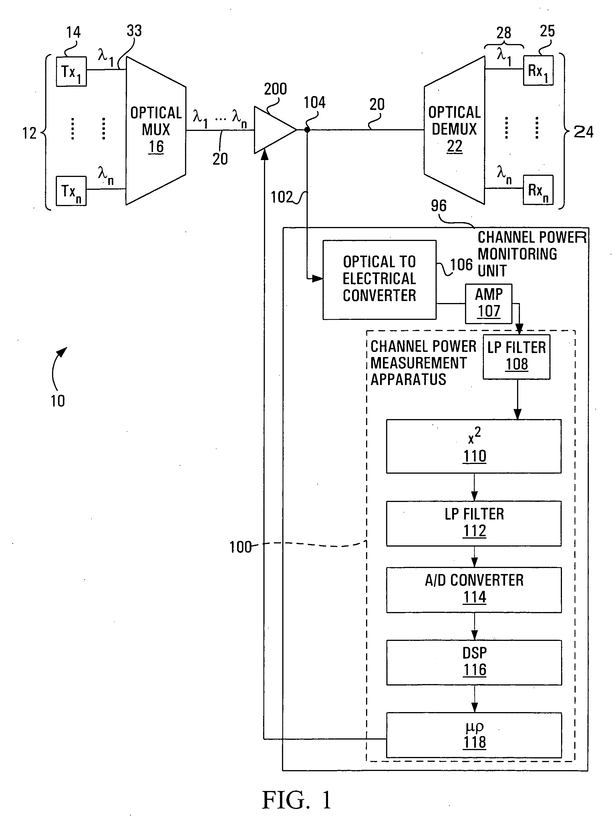
As shown in FIG. 1, a wavelength division multiplexed (WDM) network is shown generally at 10. The network 10 includes a plurality of transmitting stations, or optical transmitters 12 connected to an optical medium 20 by an optical multiplexer 16. The optical medium 20 is connected to an optical demultiplexer 22 which is further connected to a plurality of optical receivers 24. An optical amplifier such as that shown at 200 or a plurality such optical amplifiers maybe positioned at locations along the optical medium to amplify optical signals on the optical medium 20 to compensate for optical attenuation on the medium 20. Effectively, the network functions to permit optical signals produced by the optical transmitters 12 to be received at respective optical receivers 24.

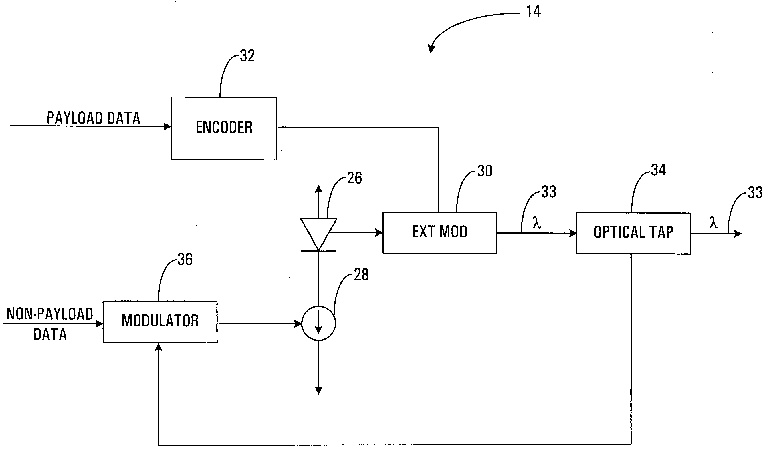
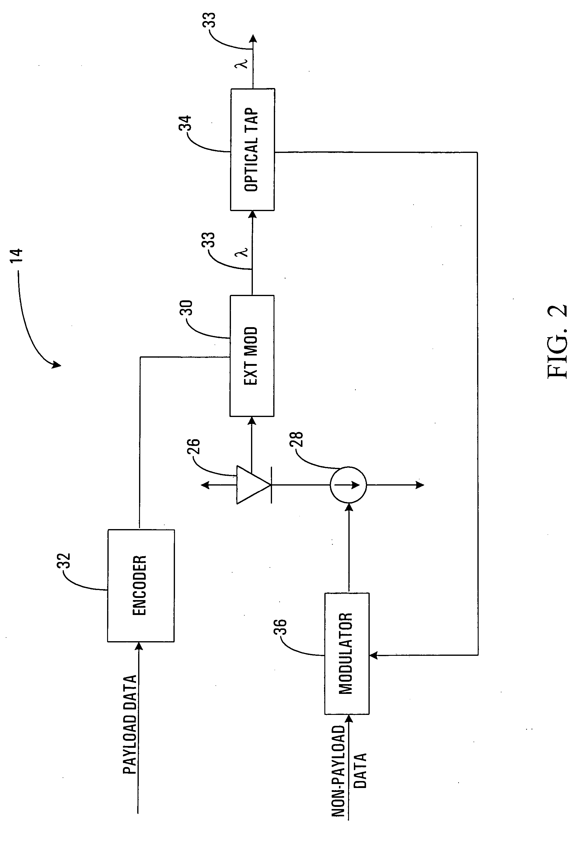
Referring to FIG. 2, a first transmitter is shown generally at 14. The first transmitter 14 is representative of each of the optical transmitters 12 shown in FIG. 1.

The first transmitter 14 includes an optical so...


PUM


Abstract

A method and apparatus for encoding optical power and non-payload data in an optical signal is described. The method involves producing a dither modulating signal having an amplitude of indicative of the optical power in the optical signal and having a phase representing the non-payload data, and modulating the optical signal with the dither modulating signal. The apparatus involves a waveform generator for producing an amplitude adjusted waveform having an amplitude responsive to the optical power of the optical signal and a binary phase shift keying modulator for binary phase shift keying the amplitude adjusted waveform in response to the non-payload data to produce a dither modulating signal having an amplitude indicative of the optical power in the optical signal and having a phase representing the non-payload data.

Description

FIELD OF THE INVENTION The present invention relates to signal encoding, and more particularly to a method and apparatus for encoding and decoding optical power and non-payload data in an optical signal. BACKGROUND OF THE INVENTION In modern communications networks, communications traffic is often carried on optical fibers. A plurality of transmitters may be connected to a first end of a fiber through an optical multiplexer to transmit a corresponding plurality of optical payload signals thereon. Each transmitter includes a semiconductor laser whose output optical intensity is modulated between a first predefined intensity representing a logical “0” and a second predefined intensity representing a logical “1” to generate an optical payload signal. Using a method called wavelength division multiplexing (WDM), the lasers transmitting on the fiber are chosen such that each laser generates a signal having a unique optical wavelength, permitting a plurality of payload signals to be opt...

Claims


Application Information

Patent Timeline
Patent Type & Authority Applications(United States)
IPC IPC(8): H04B10/04H04B10/12H04B10/155
CPCH04B10/5161H04B10/541H04L27/22H04L27/2096H04B10/5561
Inventor WAN, PING WAI
Owner CIENA
Why Eureka
Try Eureka