Developing unit and image forming device having the developing unit

a technology of developing unit and image forming device, which is applied in the direction of instruments, electrographic process devices, optics, etc., can solve the problems of increasing manufacturing costs, difficult attachment methods, and limited use of coil springs, so as to achieve simple structure, reduce manufacturing costs, and not take up space

Inactive Publication Date: 2005-03-03
MURATA MASCH LTD
View PDF10 Cites 55 Cited by
  • Summary
  • Abstract
  • Description
  • Claims
  • Application Information

AI Technical Summary

Benefits of technology

[0009] By the above-described configuration, since a wiring structure can be formed only by the wire rod in the developing unit, the wiring structure has an extremely simple structure and does not take up space. That is, if the wire rod is bent appropriately and disposed in a vacant space, the space can be utilized more efficiently and the device can be downsized. In addition, by changing the attaching hole of the supporting plate member, a contact position for the outer connection can be changed easily, and the device can be designed more freely. Such a change can be dealt with easily by adjusting the length of the wire rod. By the elastic force of the wire rod, the contact member is connected electrically with the impressed member. A part of the wire rod is exposed as the contact part from the attaching hole of the supporting member. Therefore, the supporting plate member can be attached easily. That is, the supporting plate member can be attached by bending the wire rod, and a sheet metal processing is not necessary to be carried out as in the case of the leaf spring.
[0010] Furthermore, when attaching the supporting plate member, if the contact member is set to be pressed by the impressed member, an electrical connection can be made easily. In addition, by forming one end part of the contact member in the coil spring shape, the electrical connection can be made reliable and stable. Moreover, by forming the groove on the inner surface of the supporting plate member and fitting the contact member in the groove, the contact member can be supported in a stable manner.

Problems solved by technology

By the wiring structure processed into the coil spring shape used in the first conventional image forming device, an attaching method is difficult.
According to the second conventional image forming device, a structure for inserting in the coil spring becomes necessary, and a place where the coil spring can be used becomes limited.
In addition, a sheet metal processing becomes necessary for the electrode structure formed by the leaf spring and the manufacturing costs increase.

Method used


Image

  • Developing unit and image forming device having the developing unit
  • Developing unit and image forming device having the developing unit
  • Developing unit and image forming device having the developing unit

Examples


Embodiment Construction

[0057] An embodiment of the present invention will be described. The embodiment to be described below is a preferable specific example for implementing the present invention. Therefore, there are various technical limitations in the description. However, unless explicitly stated in the flowing description to limit the present invention, the present invention shall not be limited to the embodiments.

[0058] (Entire Structure of an Image Forming Device)

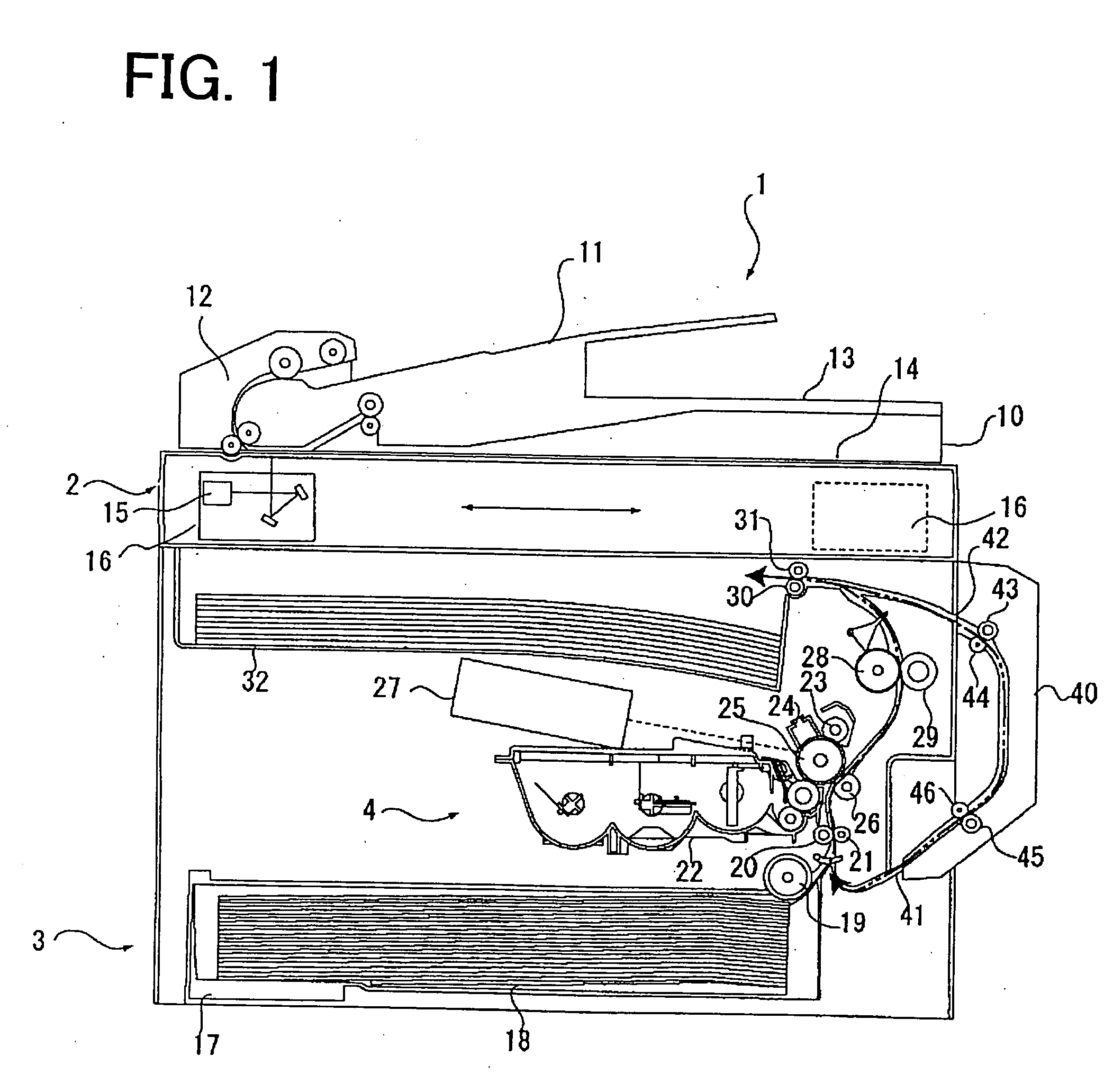
[0059]FIG. 1 is a schematic cross-sectional view of the entire image forming device according to an embodiment of the present invention. In an upper part of an image forming device 1, a document scanning unit 2 is disposed. In a lower part of the image forming device 1, a paper feed unit 3 and a printing unit 4 are disposed in this order from a bottom surface.

[0060] In the document scanning unit 2, an original document placed on a document tray 11 is transported to a scanning position by a document transportation device 12 and discharg...


PUM


Abstract

A developing unit includes an impressed member to which a voltage is impressed, a contact member which is made of a metal wire rod and urged by an elastic force to make contact with the impressed member and to be connected electrically with the impressed member, and a supporting plate member which supports the contact member at an inner surface side and exposes a part of the contact member as a contact part for an outer connection to an outer surface from an attaching hole.

Description

BACKGROUND OF THE INVENTION [0001] 1. Field of the Invention [0002] The present invention relates to a developing unit used in an image forming device such as a copy machine, a printer and a facsimile machine for adhering a developer on an electrostatic latent image and developing the electrostatic latent image, and to an image forming device having the developing unit. [0003] 2. Description of the Related Art [0004] In the above-described image forming device, when developing an electrostatic latent image, a bias voltage is impressed or a voltage is impressed for charging a developer (toner). An electrical wiring becomes necessary for the impressing operation. As an example of such a wiring, according to a first conventional image forming device, a bias electrode consisting of a piano wire, a stainless steel wire for a spring, a phosphor bronze wire or the like is provided on a sleeve flange. One end of the bias electrode is formed in a coil spring shape and makes contact with an e...

Claims


Application Information

Patent Timeline
Patent Type & Authority Applications(United States)
IPC IPC(8): G03G15/08G03G15/06
CPCG03G15/0812
Inventor KAWAI, HIDEAKI
Owner MURATA MASCH LTD
Why Eureka
Try Eureka