Switch circuit and composite high-frequency part

a high-frequency part and switch circuit technology, applied in the direction of electrical equipment, transmission devices, coupling devices, etc., can solve the problems of malfunction of the circuit parts, signal leakage to the receiving circuit, and sometimes disconnected mobile phones

Inactive Publication Date: 2005-03-03
MURATA MFG CO LTD
View PDF2 Cites 35 Cited by
  • Summary
  • Abstract
  • Description
  • Claims
  • Application Information

AI Technical Summary

Problems solved by technology

According to recent rapid expansion of mobile phones, however, a frequency band allocated to each system cannot allow all users to use their mobile phones in major cities in advanced countries, resulting in difficulty in connection and thus causing such a problem that mobile phones are sometimes disconnected during communication.
In addition, the resonance frequency may be changed by the unevenness of the capacitance of the capacitor cd4 and a capacitance component parasitic to the transmission line ld3, resulting in further increase in a signal leaking to the receiving circuits of GSM 1800 and GSM 1900.
In the case of tra...

Method used


Image

  • Switch circuit and composite high-frequency part
  • Switch circuit and composite high-frequency part
  • Switch circuit and composite high-frequency part

Examples


first embodiment

[1] First embodiment

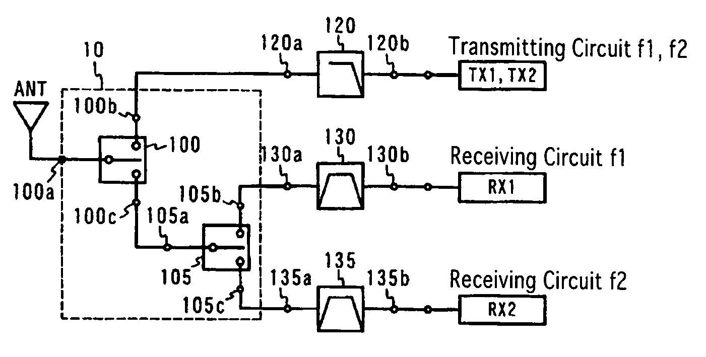
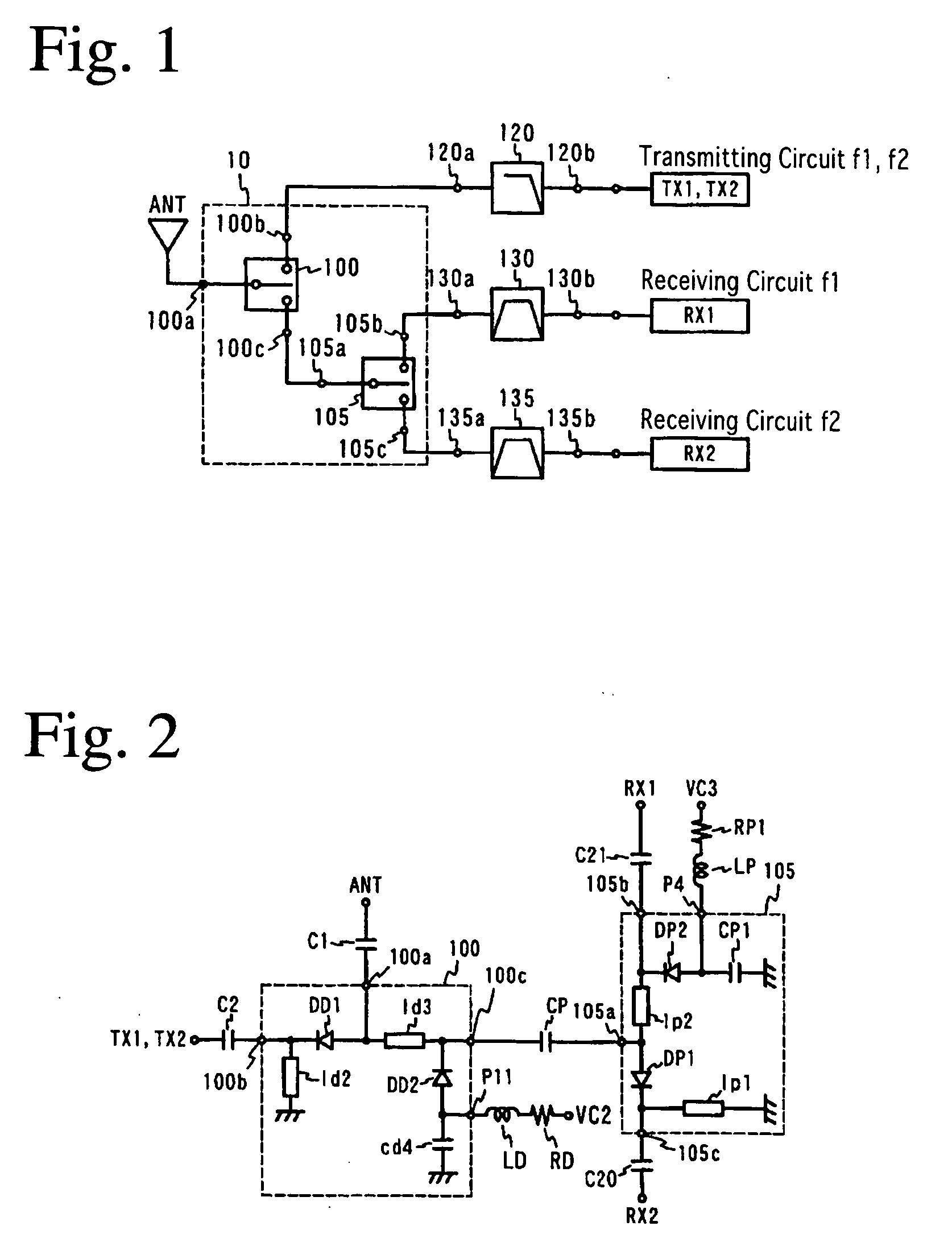
FIG. 1 shows a high-frequency circuit comprising a switch circuit according to one embodiment of the present invention, and FIG. 2 shows the equivalent circuit of the switch circuit. It is assumed below for the simplification of explanation without intention of restricting the present invention that among pluralities of communication systems, a first communication system f1 is GSM 1800 (transmitting frequency: 1710 to 1785 MHz, receiving frequency: 1805 to 1880 MHz), and a second communication system f2 is GSM 1900 (transmitting frequency: 1850 to 1910 MHz, receiving frequency: 1930 to 1990 MHz).

This switch circuit is constituted by a first switch 100 and a second switch 105 both comprising switching elements, inductors and a capacitor. The first switch 100 comprises a first port 100a connected to an antenna circuit, a second port 100b connected to transmitting circuit of GSM 1800 and GSM 1900, and a third port 100c connected to a second switch 105. The second ...

second embodiment

[2] Second Embodiment

With respect to a switch circuit according to a second embodiment of the present invention, detailed explanation will be made below in a case where a first communication system is GSM 1800 (transmitting frequency: 1710 to 1785 MHz, receiving frequency: 1805 to 1880 MHz), and a second communication system is GSM 1900 (transmitting frequency: 1850 to 1910 MHz, receiving frequency: 1930 to 1990 MHz), like the first embodiment. Incidentally, because the equivalent circuit of the switch circuit in this embodiment shares many common parts with that of the first embodiment, explanation will be concentrated on different parts for simplification.

The equivalent circuit of this switch circuit is shown in FIG. 8. Though it does not differ from the switch circuit of the first embodiment in an equivalent circuit, it is opposite to the first embodiment in the connection of the receiving circuits of GSM 1900 and GSM 1800 and the fifth and sixth ports in the second switch; th...

third embodiment

[3] Third Embodiment

A switch circuit according to a third embodiment of the present invention will be explained below. Because the equivalent circuit of the switch circuit in this embodiment shares many parts with that of the second embodiment, explanation will be concentrated on different parts for simplification.

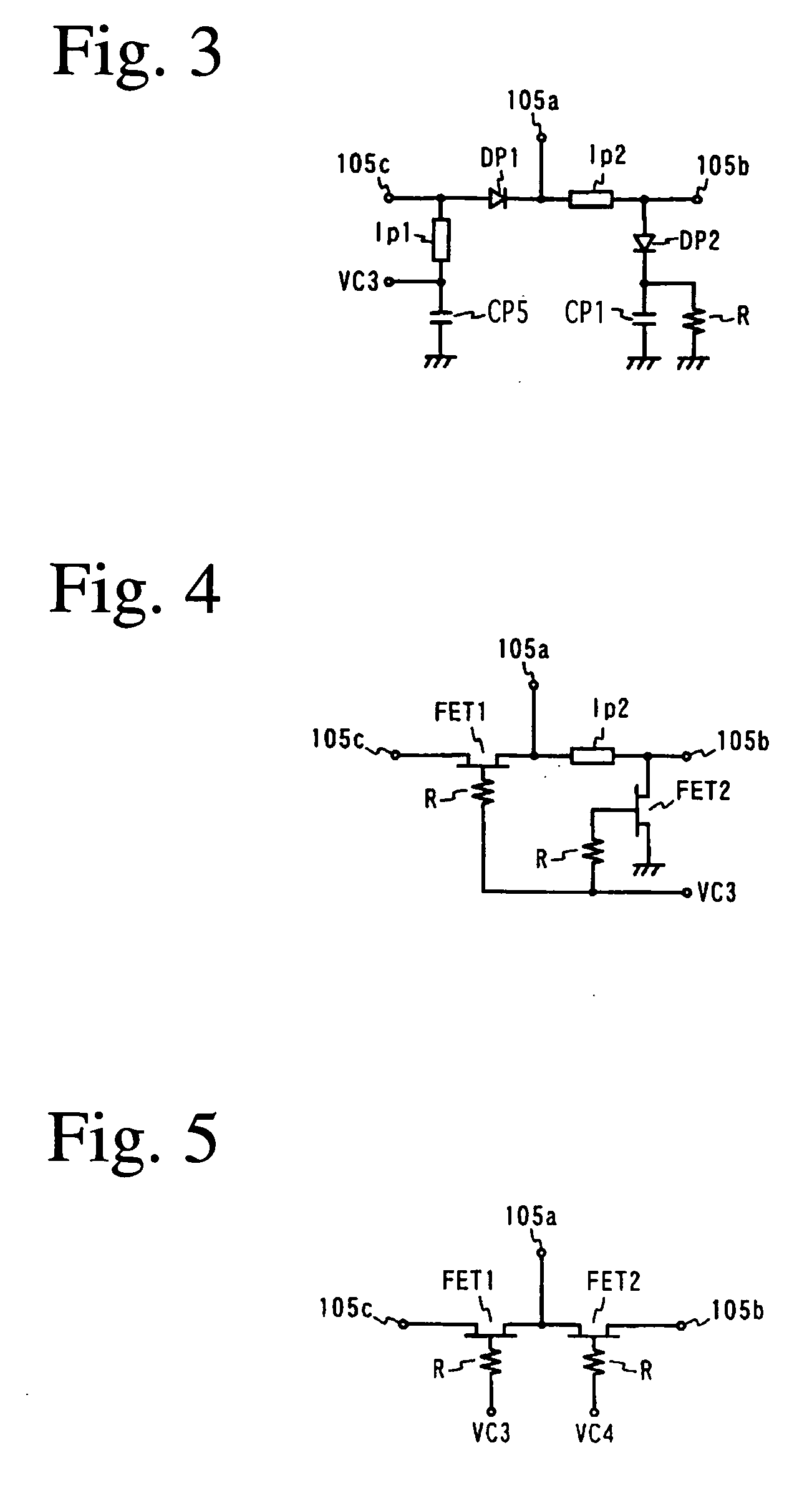
The equivalent circuit of this switch circuit is shown in FIG. 9. The equivalent circuit of this switch circuit differs from that of the second embodiment in that a capacitor CP5 is disposed between the transmission line lp1 of the second switch 105 and the ground, and that a control circuit VC2 is connected between this transmission line lp1 and the capacitor CP5 via an inductor and a resistor.

When the switch circuit in this embodiment is operated according to the same control logic of the control circuits VC2, VC3 as in the second embodiment, reverse voltage is applied to the diodes DP1, DP2 of the second switch 105 in the transmitting mode of GSM 1800 / GSM 1900, res...


PUM


Abstract

A switch circuit for selectively switching connection of an antenna side circuit with a reception circuit and a transmission circuit of two communication systems one of which has a reception frequency band partially overlapped with a transmission frequency of the other. The switch circuit includes (a) a first switch unit for switching connection of the antenna side circuit with the transmission circuit side of the first and tie second communication systems and the reception circuit side of the first and the second communication system and (b) a second switch unit connected between the first switch unit and the reception circuit of the first and the second communication system for switching connection of the antenna side circuit with the reception circuit of the first and the second communication system. (c) The transmission circuit side of the first and the second communication system of the first switch unit is connected to a transmission circuit shared by the first and the second communication system. (d) When the transmission circuit of the first and the second communication system is connected to the antenna side circuit, the second switch unit cuts off the connection between the reception circuit of the first communication system and the first switch unit.

Description

FIELD OF THE INVENTION The present invention relates to a switch circuit for a multi-band mobile phone, which has a capable of making communications in plural systems, and a high-frequency composite part comprising it. BACKGROUND OF THE INVENTION There are various systems for mobile phones, for instance, EGSM (extended global system for mobile communications) and DCS (digital cellular system) widely used mostly in Europe, GSM 850 (global system for mobile communications 850) and GSM 1900 (global system for mobile communications 1900) widely used in the U.S., and PDC (personal digital cellular system) used in Japan. According to recent rapid expansion of mobile phones, however, a frequency band allocated to each system cannot allow all users to use their mobile phones in major cities in advanced countries, resulting in difficulty in connection and thus causing such a problem that mobile phones are sometimes disconnected during communication. Thus, proposal was made to permit users ...

Claims


Application Information

Patent Timeline
IPC IPC(8): H01P1/15H04B1/40H04B1/44H04B1/48
CPCH01P1/15H04B1/005H04B1/48H04B1/44H04B1/406
Inventor KEMMOCHI, SHIGERUWATANABE, MITSUHIROFUKAMACHI, KEISUKETAI, HIROYUKI
Owner MURATA MFG CO LTD
Why Eureka
Try Eureka