Flexing multiple function interactive massage and reflexology unit

Inactive Publication Date: 2005-03-03
MAAS TECH HLDG
View PDF16 Cites 55 Cited by
  • Summary
  • Abstract
  • Description
  • Claims
  • Application Information

AI Technical Summary

Benefits of technology

[0026] Regarding the operation of the first embodiment of the shoe insole, during walking or running, the cups are alternately compressed and extended back to their original shape during sequential application of pressure as the foot is translated from the heel portion to the toe portion. The cups flatten outward as pressure is applied, providing a spring-like effect against the impact of the article of footwear against the walking or running surface. The core body provides additional cushioning and shock absorption. The pressure nub, having a reduced contacting surface area upon the foot relative to the larger contact area of the cup, essentially applies a point load to the sole of the foot.
[0027] In this manner, the pressure nubs may exhibit acupressure or reflexology characteristics wherein the nerve endings in the foot may be stimulated. Under reflexology theory, these stimulated nerve endings communicate with specific organs of the body via nerve connections to stimulate the organ. Due to the spacing of the cups away from the top surface, improved air circulation may occur as inte

Problems solved by technology

Although the hollow humps provide a massaging effect to the user's foot, unless permanently mounted to the sole on the inside of the shoe, the insole may slide around in the shoe, creating the risk of blistering of the top and sides of the foot as it rubs against the shoe.
Although the air cushion of the reference allows for the tuning and optimization of the shoe's cushioning characteristics, the air cushion suffers from the inability to provide massaging of the bottom of the feet during use.
Furthermore, the air cushion of the reference fails to provide any means for circulating air within the insole to reduce the problem of perspiration and heat buildup within the shoe.
Furthermore, due to the relatively large size of the projections, the user may experience physical strain and discomfort, especially at the ball of the foot because this area of the foot typically bears against the insole even while the foot is resting flat.
Although the device in the reference features a high degree of controllability and is capable of being optimized for a particular wearer and activity, the combination of many chambers, valves, and the CPU necessarily translates into a highly complex system which is of high cost and has decreased reliability compared to passive cushioning systems.
Moreover, such a device lacks any massaging and ventilation characteristics featured by simpler devices of the prior art.
Although the cushioning air-sack of the reference may be effective in providing enhanced air circulation inside the insole of the

Method used


Image

  • Flexing multiple function interactive massage and reflexology unit
  • Flexing multiple function interactive massage and reflexology unit
  • Flexing multiple function interactive massage and reflexology unit

Examples


first embodiment

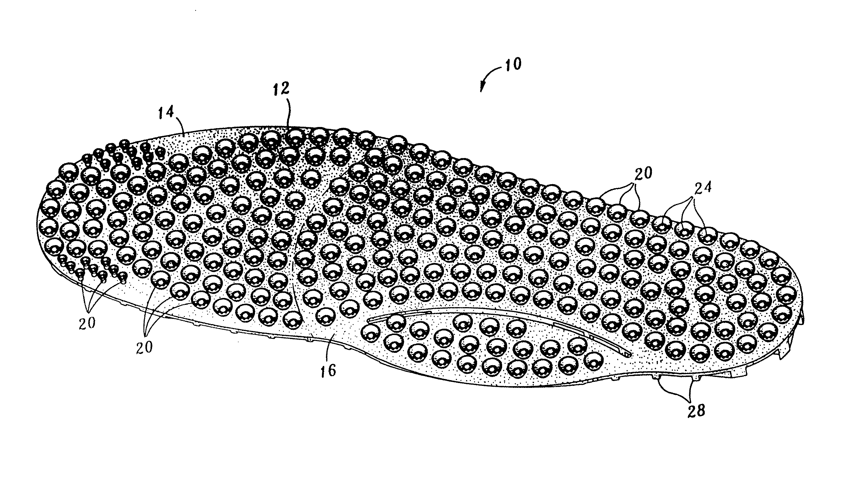
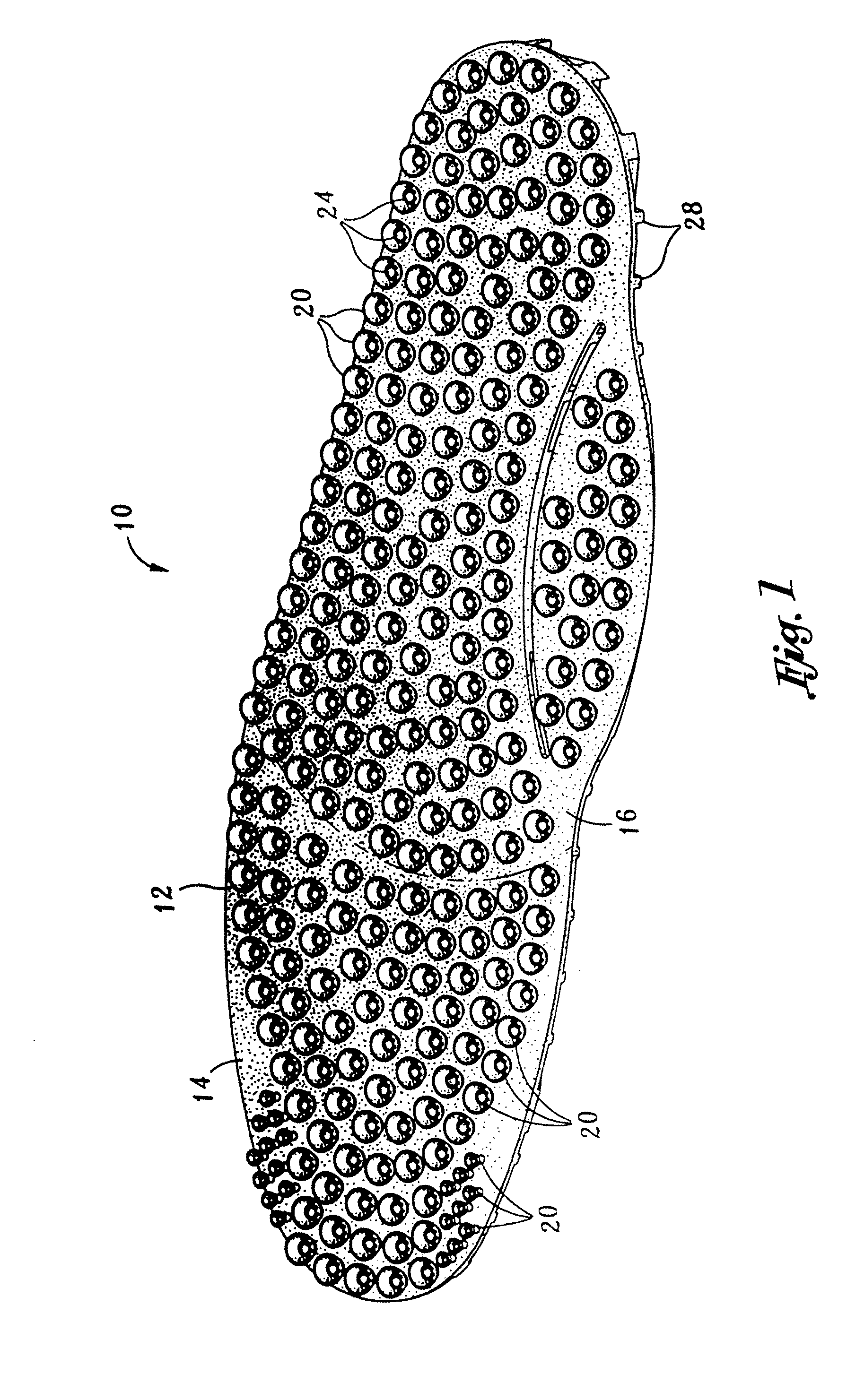
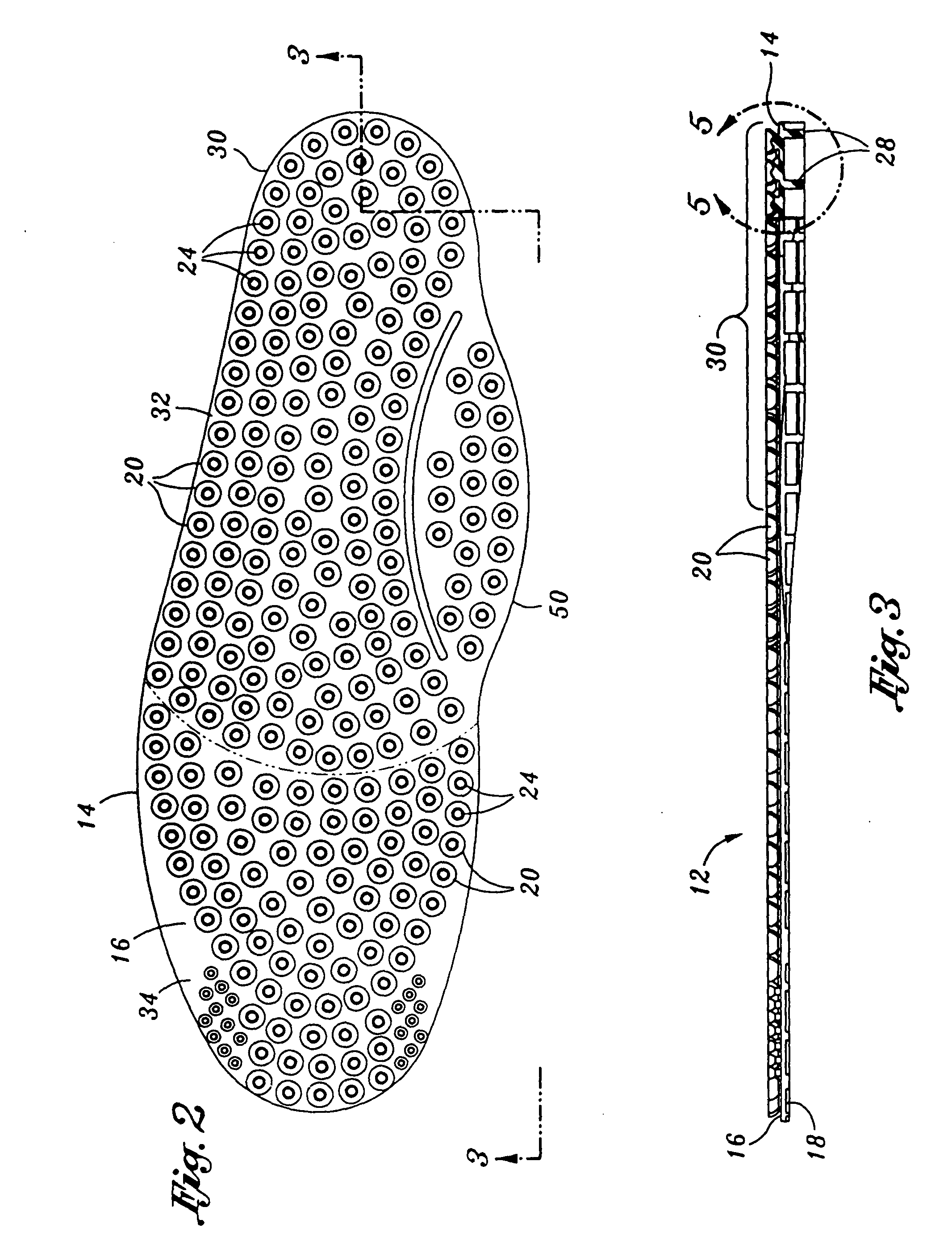
[0047] In FIG. 1, shown is the massaging and reflexology system 10 as incorporated into the shoe insole 12 in the FIG. 2 is a plan view illustrating the arrangement of a plurality of cups 20 disposed on a top surface 16 of the shoe insole 12. The massaging and reflexology system 10 is comprised of a core body 14 defining opposing top and bottom surfaces 16, 18, and a plurality of cups 20 disposed on the top surface 16. Optionally, bumps or pressure nubs 24 may be disposed within each one of the cups 20.

[0048] As can be seen in FIG. 2, each cup 20 defines a substantially concave surface 22 projecting outwardly from the top surface 16. The respective bump or pressure nub 24 is centrally disposed on the concave surface 22 of each one of the cups 20. As will be discussed in more detail below, the cups 20 provide a general cushioning and massaging benefit to the soles of the feet during use as the cups 20 are compressed during walking or running. The pressure nubs 24 provide a reflexolo...

second embodiment

[0082] the massaging and reflexology system 10 adapted for use in hand-held implements 36 will now be described. In FIG. 11, shown is a perspective view of the massaging and reflexology system 10 as incorporated into the hand-held implement 36. As was earlier mentioned, the hand-held implement 36 may include hand grips for tennis rackets, golf clubs and other sporting implements, hand held stress balls, rolling massaging bars for feet and body, and steering wheel covers. However, it is contemplated that the massaging and reflexology system 10 may be incorporated into any device that is applied to or that may bear against the wearer or user's body.

[0083] In FIG. 12, a sectional view taken along line 12-12 of FIG. 11 illustrates the arrangement of the cups 20 on the outer surface 54 of the second embodiment. As can be seen in FIG. 10, the implement 36 includes a shaft portion 38 which forms the handle grip 40 for the implement 36. The shaft portion 38 may be partially comprised of sil...


PUM

PropertyMeasurementUnit
Lengthaaaaaaaaaa
Thicknessaaaaaaaaaa
Pressureaaaaaaaaaa

Abstract

Disclosed is a massaging and reflexology system for an article of footwear comprising a core body generally configured in the shape of a shoe insole, a plurality of cups disposed on a top surface of the shoe insole, and a respective bump or pressure nub disposed within each of the cups. The cups may be disposed on a bottom surface of the core body. The shoe insole may define toe, intermediate, heel and arch portions, or any combination thereof. Each cup may define a substantially concave surface projecting outwardly from the top surface with the cup perimeters being generally circular. The pressure nubs may be centrally disposed on the concave surface of each one of the cups on the top surface. The core body, the cups, the cup spacers and the pressure nubs may be formed as a unitary structure of resilient, elastomeric material such as silicone gel.

Description

CROSS-REFERENCE TO RELATED APPLICATIONS [0001] (Not Applicable) STATEMENT RE: FEDERALLY SPONSORED RESEARCH / DEVELOPMENT [0002] (Not Applicable) BACKGROUND OF THE INVENTION [0003] The present invention pertains generally to a cushioning system for an article worn or held by a user and, more particularly, to a uniquely configured massaging and reflexology system for an article of footwear, for a hand-held implement, or for use with other articles that may be placed into contact with the body. The massaging and reflexology system is specifically configured to provide the combined therapeutic benefits of shock absorption and reflexology to a user's feet, hands or other parts of the body while simultaneously providing the benefits of air circulation to remove perspiration and dissipate body heat as well as providing muscle stimulation and blood circulation. [0004] There is currently known in the prior art, cushioned insoles for footwear to provide shock absorption to the feet. The cushion...

Claims


Application Information

Patent Timeline
IPC IPC(8): A43B17/02A61H7/00A61H39/04A63B59/00
CPCA43B7/142A43B7/146A43B17/02A43B17/08A43B17/14A61H7/001A63B59/0014A61H39/04A61H2009/0064A61H2201/1284A61H2205/065A61H2205/12A61H2205/125A61H9/0057A61H2201/1695A63B60/06A63B60/08A63B60/10
Inventor BEIRUTI, AHMAD M.
Owner MAAS TECH HLDG
Why Eureka
Try Eureka