Microcomputer having security function
- Summary
- Abstract
- Description
- Claims
- Application Information
AI Technical Summary
Benefits of technology
Problems solved by technology
Method used
Image
Examples
first embodiment
[0032] (First Embodiment)
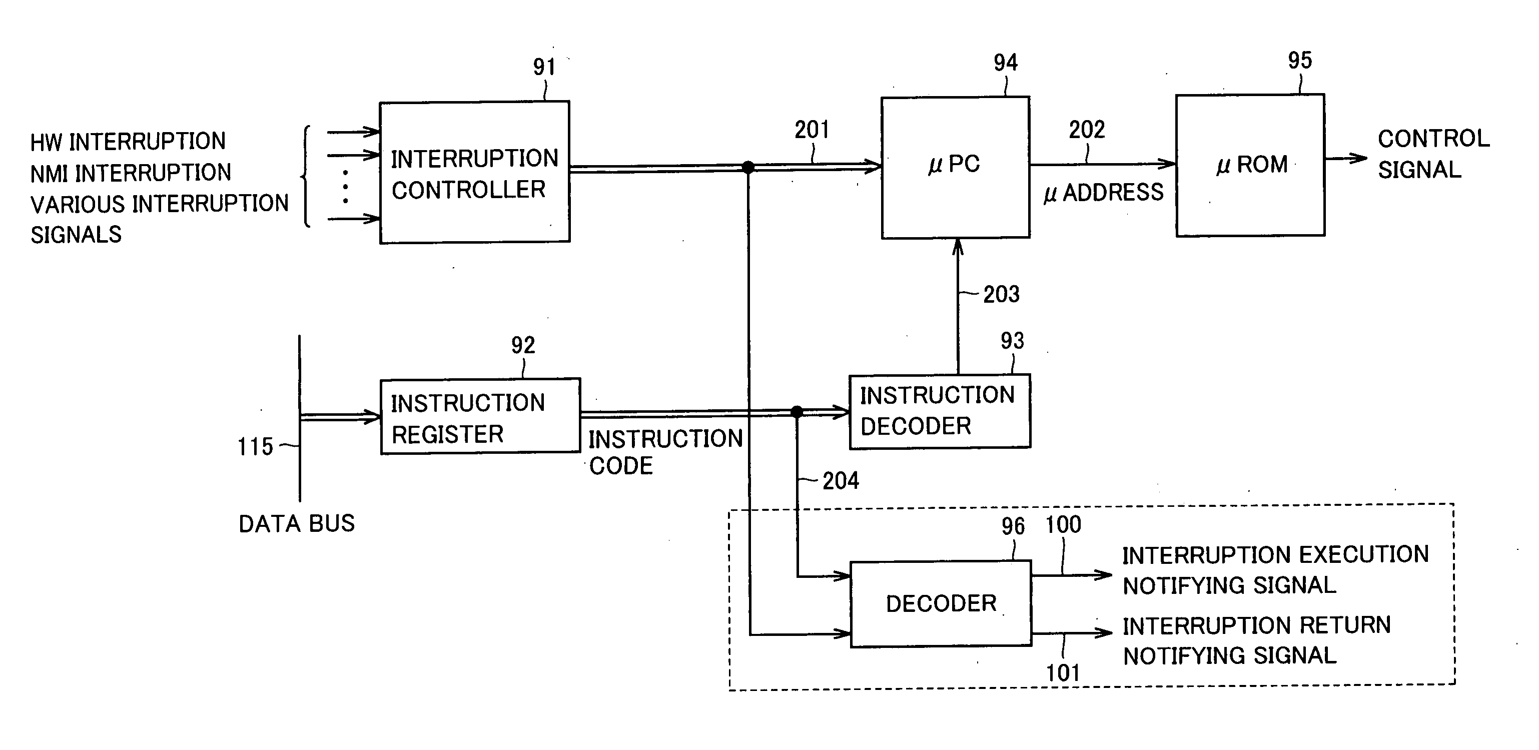
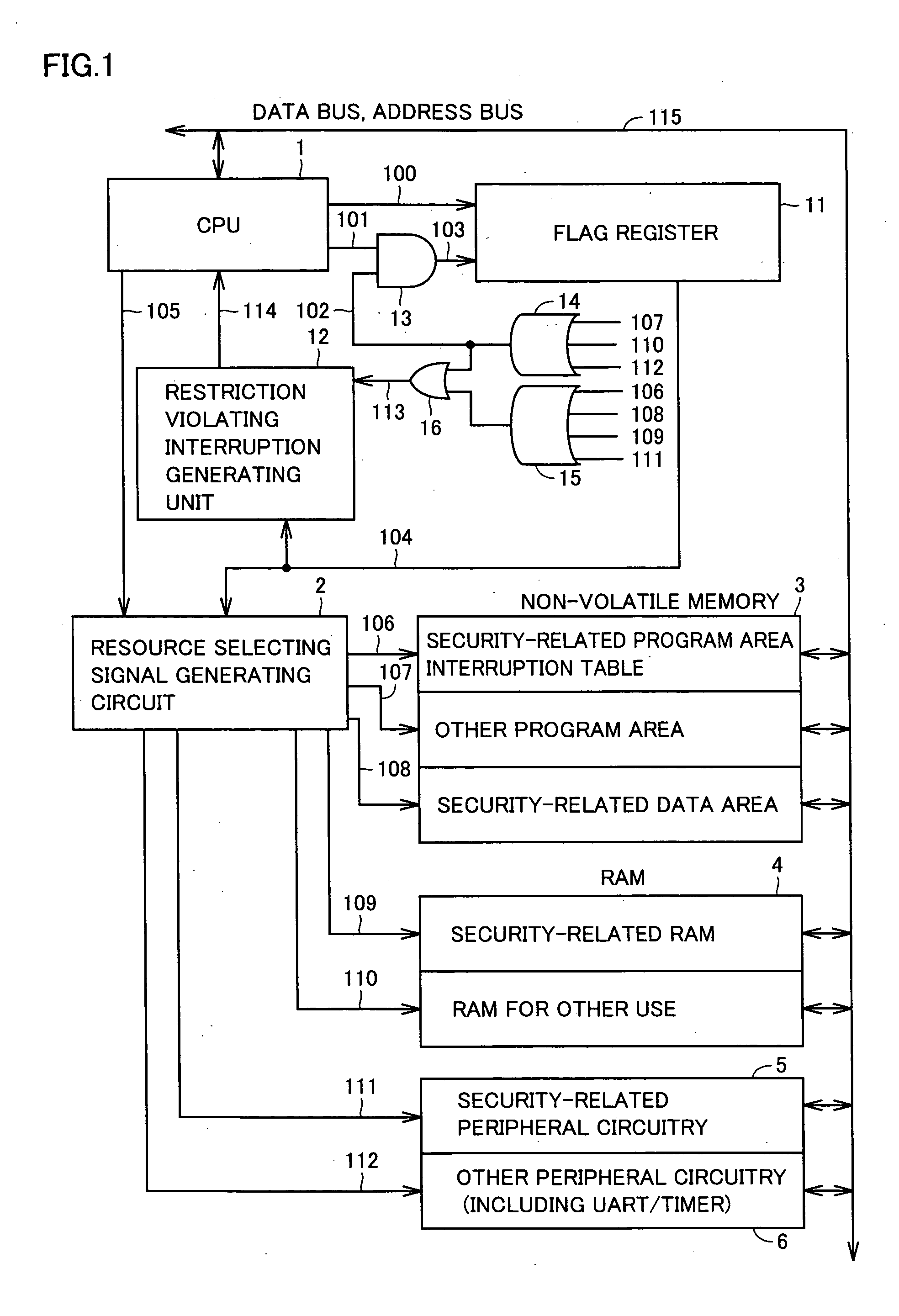
[0033]FIG. 1 is a block diagram schematically representing a configuration of a microcomputer in accordance with a first embodiment of the present invention. The microcomputer includes a CPU 1, a resource selecting signal generating circuit 2 generating a signal for selecting a resource such as a memory and peripheral circuitry, a non-volatile memory 3, an RAM (Random Access Memory) 4, security-related peripheral circuitry 5 including an encryption circuit, a random number generating circuit or the like, security-unrelated peripheral circuitry 6 including an UART (Universal Asynchronous Receiver-Transmitter), a timer or the like, a flag register 11, a restriction violating interruption generating circuit 12, an AND circuit 13, and OR circuits 14 to 16.
[0034] Non-volatile memory 3 includes a security-related program area and an interruption table (hereinafter simply referred to as a security-related program area), other program areas, and a security-related ...
second embodiment
[0059] (Second Embodiment)
[0060]FIG. 5 is a block diagram schematically representing a configuration of a microcomputer in accordance with a second embodiment of the present invention. Different from the microcomputer in accordance with the first embodiment shown in FIG. 1, flag register 11 is replaced by a counter 17, the interruption return notifying signal is directly input to counter 17 and OR circuits 14 to 16 are replaced by an OR circuit 18. Though OR circuits 14 to 16 shown in FIG. 1 are replaced by OR circuit 18, the configuration is logically equivalent.
[0061] When interruption execution notifying signal 100 output from CPU 1 is rendered active, counter 17 increments the count value by 1, and when interruption return notifying signal 101 output from CPU 1 is rendered active, counter 17 decrements the count value by 1. When the count value is “0”, counter 17 outputs “1” to security-related access prohibiting signal 116, and when the count value is “1” or larger, counter 17...
third embodiment
[0070] (Third Embodiment)
[0071]FIG. 7 is a block diagram schematically representing a configuration of a microcomputer in accordance with a third embodiment of the present invention. Different from the microcomputer in accordance with the second embodiment shown in FIG. 5, a flag register 11 and an AND circuit 19 are added, and setting of flag register 11 is done by CPU 1.
[0072] At the time of a program switching, CPU 1 sets “0” in flag register 11 when a program not related to encryption or the like is switched to an encryption-related program, and sets “1” in flag register 11 when an encryption-related program is switched to a program not related to encryption or the like. In the present embodiment, it is assumed that transition from a program not related to encryption or the like to an encryption-related program is not caused by execution of an interruption program.
[0073] AND circuit 19 outputs a logical product of a security-related access prohibiting signal 104 output from fl...
PUM
 Abstract
Description
Claims
Application Information
 - R&D
- Intellectual Property
- Life Sciences
- Materials
- Tech Scout
- Unparalleled Data Quality
- Higher Quality Content
- 60% Fewer Hallucinations
Browse by: Latest US Patents, China's latest patents, Technical Efficacy Thesaurus, Application Domain, Technology Topic, Popular Technical Reports.
© 2025 PatSnap. All rights reserved.Legal|Privacy policy|Modern Slavery Act Transparency Statement|Sitemap|About US| Contact US: help@patsnap.com


