Method and system for starting up fuel cell stack at subzero temperatures, and method of designing fuel cell stack

a fuel cell and subzero temperature technology, applied in the direction of cell components, cell component details, electrochemical generators, etc., can solve the problems of abrupt voltage drop, considerable time required before startup is achieved, and considerable time is required to achieve the effect of starting up and running at subzero temperatures, excellent effect, and keeping the degree of freedom

Inactive Publication Date: 2005-03-10
HONDA MOTOR CO LTD
View PDF8 Cites 92 Cited by
  • Summary
  • Abstract
  • Description
  • Claims
  • Application Information

AI Technical Summary

Benefits of technology

[0017] According to this start-up method, because the heat capacity of separators that are made from metal is small, the fuel cell stack warms up easily and it is possible to shorten the warm-up time of a subzero start-up.
[0050] According to the system for starting up a fuel stack at a subzero temperature of the present invention, the excellent effect is achieved that it is possible to easily set the heat capacity of the power generating section of the fuel cell stack to a heat capacity such that, in a case in which the temperature of the fuel cell stack is raised by the self-generated heat that accompanies the generation of power by the fuel cell stack, the temperature of the membrane electrode assemblies reaches 0° C. or more before the membrane electrode assemblies become unable to generate power.

Problems solved by technology

In this type of fuel cell, because the power generating efficiency is deteriorated at low temperatures, startability at low temperatures causes considerable problems.
Accordingly, when the fuel cell is used in a vehicle, if an attempt is made to start up the fuel cell when the outside temperature is low, for example, is a subzero temperature, the problem arises in that a considerable time is required before startup is achieved.
As a result of this generated water freezing inside diffusion electrode layers and catalytic layers, the problem arises in that the reaction gas is unable to reach the solid polymer electrolyte membrane, thereby inviting an abrupt voltage drop and, ultimately, hastening a drop in voltage.
Namely, regardless of how much the output current is increased, if the freezing of the generated water is more rapid than the increase in temperature provided by the self-generated heat, the fuel cell stack ends up becoming unable to generate power due to the water generated inside the cells freezing before the temperature is increased, resulting in the objective not being achieved.
Moreover, regardless of what attempts are made to increase the output current, the maximum current density that can be output in the membrane electrode assemblies that form the fuel cell is decided in accordance with the temperature, and more current than this cannot be supplied.
In addition, if water generated in the diffusion electrode layer and catalytic layer freezes and there is a failure in the startup, it is extremely difficult to once again conduct a startup operation.
However, once the holes in the diffusion electrode layer and catalytic layer have been blocked by the freezing of the generated water so that the reaction gas is unable to pass therethrough, even if reaction gas is supplied to the fuel cell stack, the reaction gas cannot reach the solid polymer electrolyte membrane and power cannot be obtained from the fuel cell stack.
If power cannot be obtained from the fuel cell stack, then it is not possible for the fuel cell stack to be warmed up by self-generated heat.

Method used


Image

  • Method and system for starting up fuel cell stack at subzero temperatures, and method of designing fuel cell stack
  • Method and system for starting up fuel cell stack at subzero temperatures, and method of designing fuel cell stack
  • Method and system for starting up fuel cell stack at subzero temperatures, and method of designing fuel cell stack

Examples


control example 1

Constant Current Generation

[0168] The flowchart shown in FIG. 20 shows a start-up control routine when the fuel cell stack 1 is started up by the aforementioned constant current power generation at a subzero temperature. This start-up control routine is executed by the ECU 20.

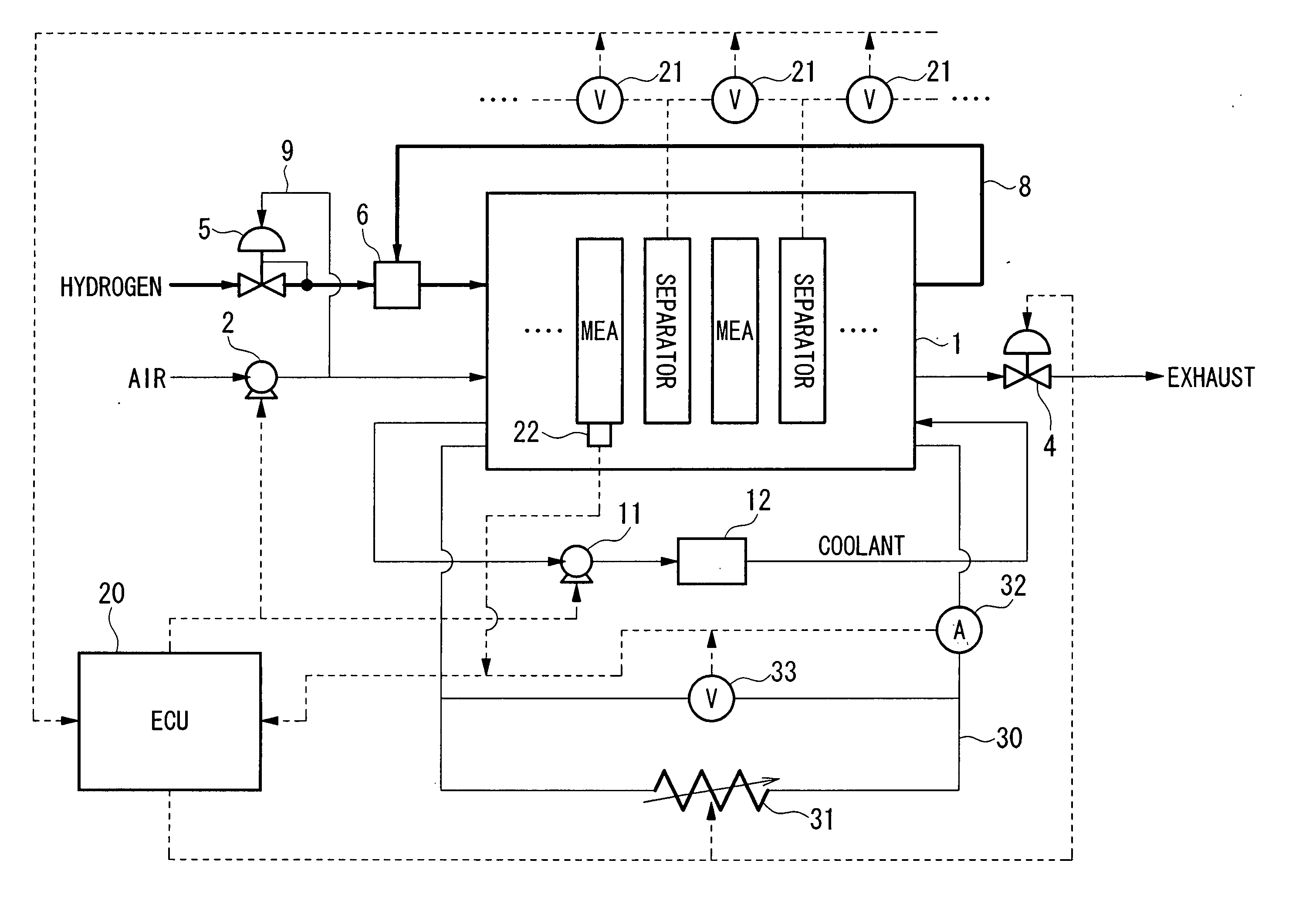
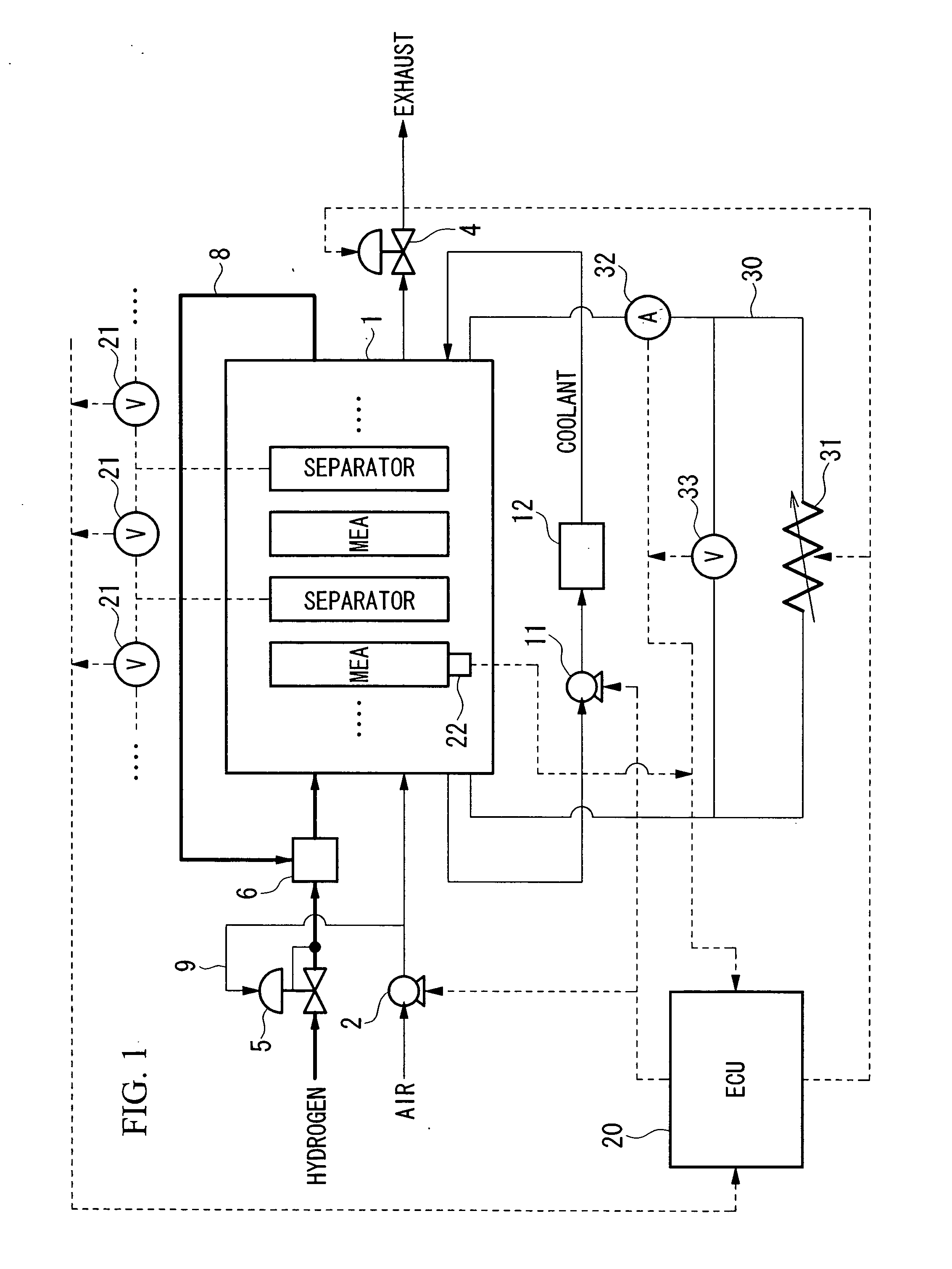
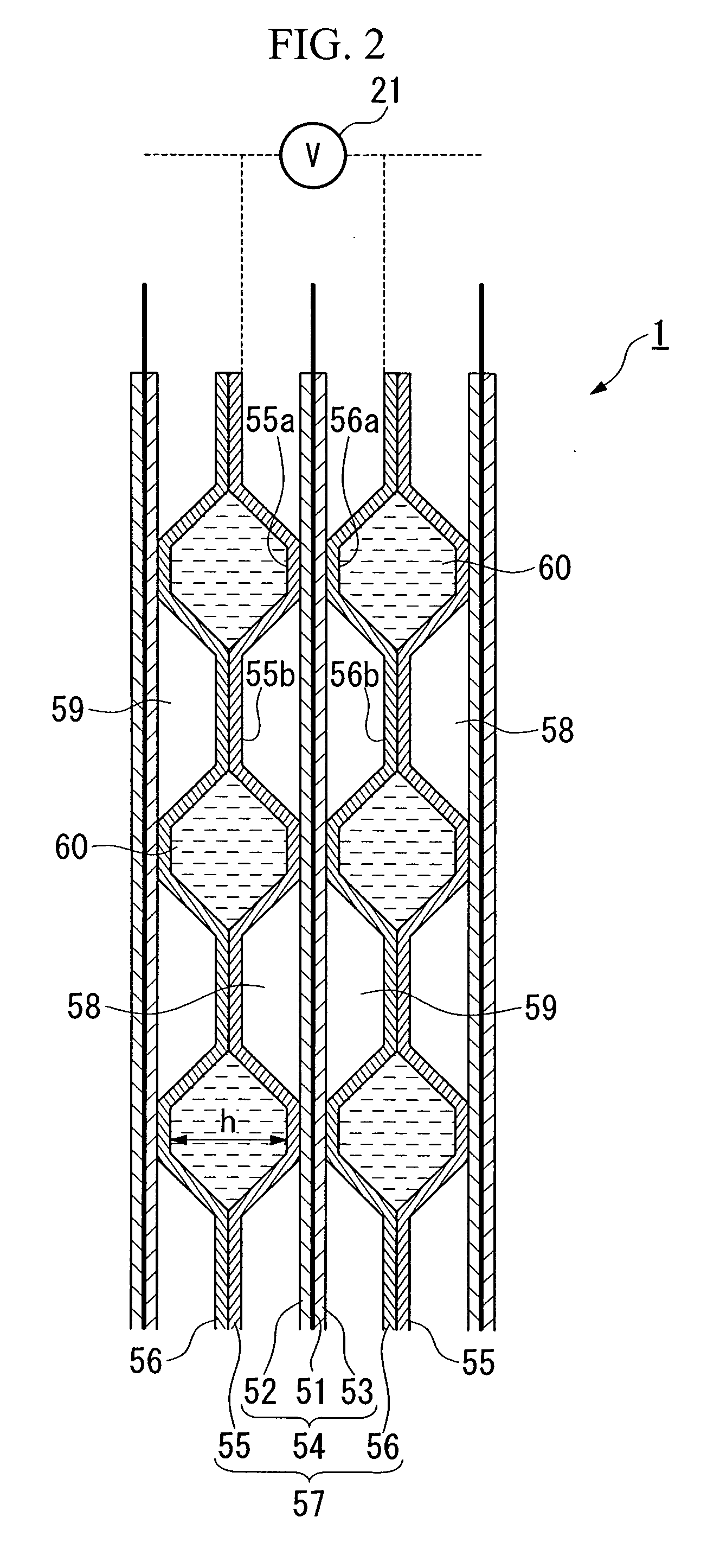
[0169] Firstly, when the ignition switch of a fuel cell vehicle is turned ON (step S201), reaction gas is supplied to the fuel cell stack 1 (step S202). Namely, the compressor 2 is operated and the pressure control valve 4 and the fuel supply control valve 5 are opened. In addition, air is supplied to the air flow passages 59 and hydrogen gas is supplied to the fuel flow passages 58 of each single cell 57 of the fuel cell stack 1.

[0170] Next, the cell voltage of each single cell 57 is measured by the respective voltage sensors 21 (step S203), and a determination is made as to whether or not the lowest cell voltage from among the measured cell voltages is larger than a first threshold voltage V1 that has been...

control example 2

[0183] The flowchart shown in FIG. 21 shows a start-up control routine when output current of the fuel cell stack 1 is controlled using suitable current values that are set between the minimum required current and the maximum obtainable current at a subzero start-up. This start-up control routine is executed by the ECU 20.

[0184] The flowchart shown in FIG. 21 is basically the same as the flowchart shown in FIG. 20, and only varies in step S219 which corresponds to step S209 in the flowchart in FIG. 20. The same step numbers are given to processing in control example 2 that is the same as that in control example 1, and a description thereof is omitted, only step S219 is described.

[0185] In control example 2, in step S219, the output current of the fuel cell stack 1 is set while referring to an output current map (not shown) that uses, for example, the internal temperature of the fuel cell stack 1 as a parameter. Note that the output current map is created in advance based on experi...

control example 3

Constant Voltage Generation

[0188] The flowchart shown in FIG. 22 shows a start-up control routine when the fuel cell stack 1 is started up by the aforementioned constant voltage power generation at a subzero temperature. This start-up control routine is executed by the ECU 20.

[0189] Firstly, when the ignition switch of a fuel cell vehicle is turned ON (step S301), reaction gas is supplied to the fuel cell stack 1 (step S302). Namely, the compressor 2 is operated and the pressure control valve 4 and the fuel supply control valve 5 are opened. In addition, air is supplied to the air flow passages 59 and hydrogen gas is supplied to the fuel flow passages 58 of each single cell 57 of the fuel cell stack 1.

[0190] Next, the cell voltage of each single cell 57 is measured by the respective voltage sensors 21 (step S303), and a determination is made as to whether or not the lowest cell voltage from among the measured cell voltages is larger than a first threshold voltage V1 that has been...


PUM

PropertyMeasurementUnit
temperatureaaaaaaaaaa
current densityaaaaaaaaaa

Abstract

A method of starting up at a subzero temperature a solid polymer electrolyte fuel cell stack that is formed by stacking a plurality of layers of separators and membrane electrode assemblies having a solid polymer electrolyte membrane and electrodes. The method includes a step of using a solid polymer electrolyte fuel cell stack in which the separators are made from metal and have a cross-sectional waveform structure, and a space that is formed between at least a portion of the separators and separators that are placed adjacent to this portion of the separators is used as a coolant flow passage.

Description

BACKGROUND OF THE INVENTION [0001] 1. Field of the Invention [0002] Priority is claimed on Japanese Patent Application No. 2003-315725, filed Sep. 8, 2003, the content of which are incorporated herein by reference. [0003] The present invention relates to a method for starting up a fuel cell stack at subzero temperatures, relates to a system for starting up a fuel cell stack at subzero temperatures, and relates to a method of designing a fuel cell stack. [0004] 2. Description of Related Art [0005] Among the fuel cells, there are those in which a solid polymer electrolyte membrane is sandwiched between an anode electrode and a cathode electrode so as to form a membrane electrode assembly. This membrane electrode assembly is further sandwiched between a pair of separators so as to form a single cell (i.e., a fuel cell unit). In this type of fuel cell, typically, a plurality of single cells are stacked and used as a fuel cell stack. [0006] In this fuel cell, a chemical reaction is cause...

Claims


Application Information

Patent Timeline
Patent Type & Authority Applications(United States)
IPC IPC(8): H01M8/02H01M2/14H01M8/04H01M8/10H01M8/24
CPCH01M8/0247Y02E60/50H01M8/04029H01M8/04097H01M8/04253H01M8/04268H01M8/04365H01M8/04395H01M8/04552H01M8/04559H01M8/04589H01M8/04731H01M8/04753H01M8/04761H01M8/04768H01M8/04776H01M8/0488H01M8/0491H01M8/0267H01M8/0258H01M8/241H01M8/04225H01M8/04302H01M8/0265
Inventor KATO, HIDEOINAI, SHIGERUHAYASHI, KATSUMIJINBA, RYO
Owner HONDA MOTOR CO LTD
Why Eureka
Try Eureka