Hybrid gas liquefaction cycle with multiple expanders

a gas liquefaction cycle and expander technology, applied in the direction of compression machines, refrigeration machines, solidification, etc., can solve the problem of very energy-intensive process of liquefaction of natural gas, and achieve the effect of reducing or eliminating the need for balan

Active Publication Date: 2005-03-17
AIR PROD & CHEM INC
View PDF18 Cites 90 Cited by
  • Summary
  • Abstract
  • Description
  • Claims
  • Application Information

AI Technical Summary

Benefits of technology

an embodiment of the invention may comprise reducing or eliminating the need for the balance refrigeration by cooling and work expanding a portion of the compressed refrigerant

Problems solved by technology

The liquefaction of natural gas i

Method used


Image

  • Hybrid gas liquefaction cycle with multiple expanders
  • Hybrid gas liquefaction cycle with multiple expanders
  • Hybrid gas liquefaction cycle with multiple expanders

Examples


example

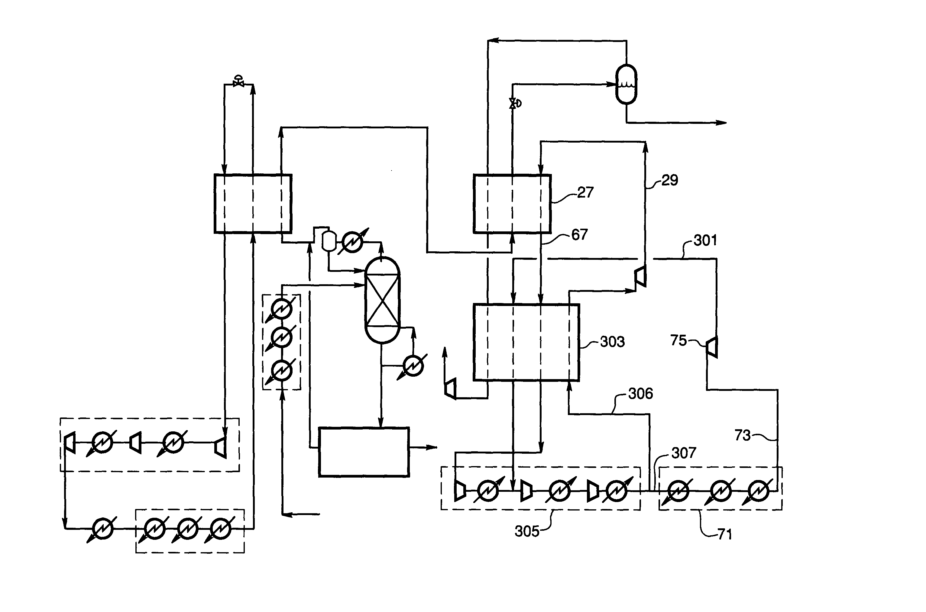
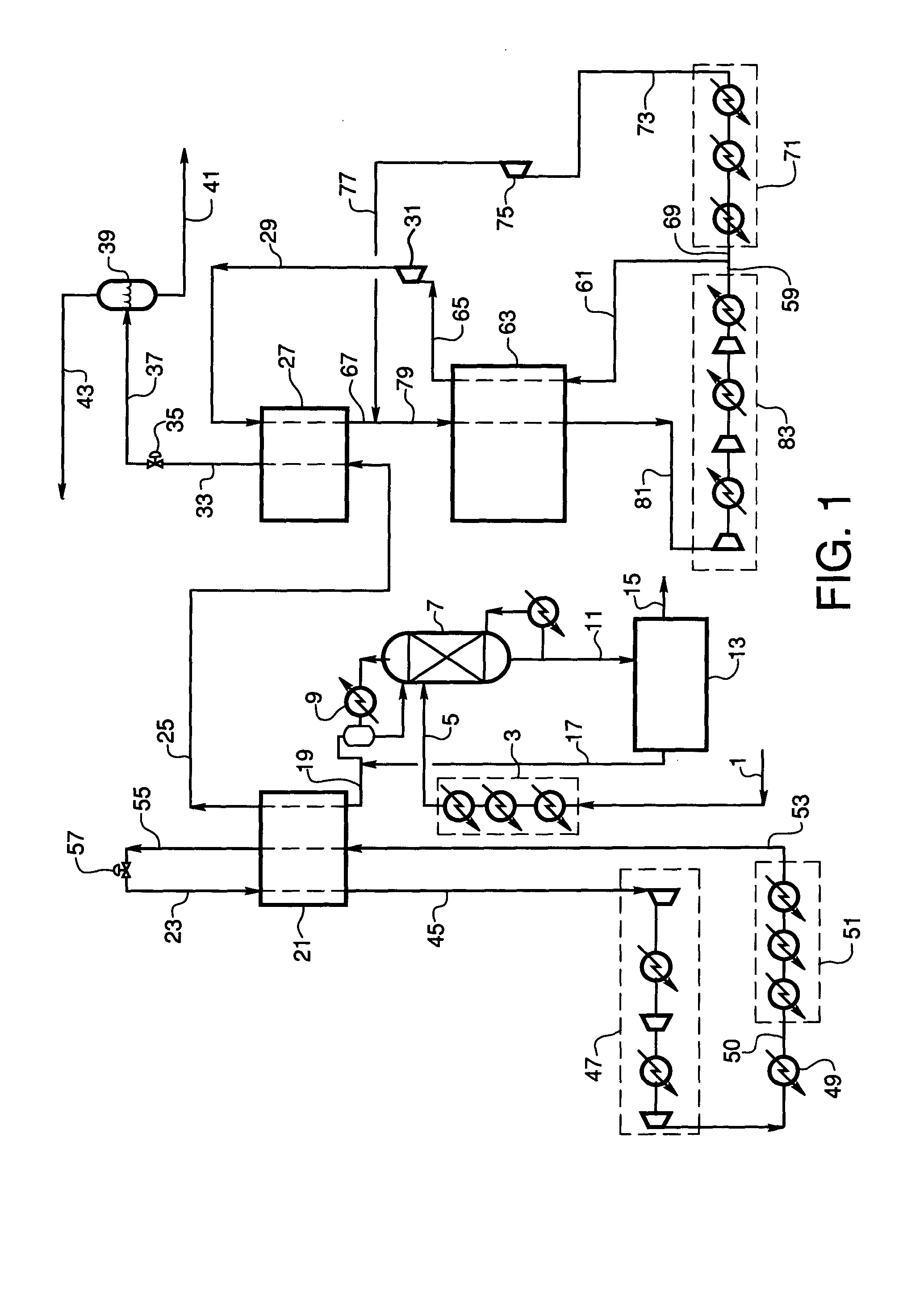
The embodiment of FIG. 1 is illustrated by the following non-limiting Example. Natural gas feed in line 1 is provided at a flow rate of 59,668 kgmoles per hour and has a composition of 3.90 mole % nitrogen, 87.03% methane, 5.50% ethane, 2.02% propane and 1.55% C4 and heavier hydrocarbons (C4+) at 27° C. and 60.3 bara. The feed has been cleaned and dried in an upstream pretreatment section (not shown), for the removal of acid gases such as CO2 and H2S along with other contaminants such as mercury. Natural gas feed in line 1 enters the first heat exchanger section 3 and is precooled to −18° C. using several levels of propane refrigeration. The precooled natural gas feed stream in line 5 enters scrub column 7 where the heavier components of the feed, pentane and heavier hydrocarbons, are removed to prevent freezing in the liquefaction process. The scrub column has an overhead condenser 9 which also uses propane refrigeration to provide the reflux to the scrub column. The bottoms produ...


PUM


Abstract

Method for gas liquefaction comprising cooling a feed gas by a first refrigeration system in a first heat exchange zone and withdrawing a substantially liquefied stream therefrom, further cooling the substantially liquefied stream by indirect heat exchange with one or more work-expanded refrigerant streams in a second heat exchange zone, and withdrawing therefrom a further cooled, substantially liquefied stream. At least one of the one or more work-expanded refrigerant streams is provided by compressing one or more refrigerant gases to provide a compressed refrigerant stream, cooling all or a portion of the compressed refrigerant stream in a third heat exchange zone to provide a cooled, compressed refrigerant stream, and work expanding the cooled, compressed refrigerant stream to provide one of the one or more work-expanded refrigerant streams. The flow rate of a work-expanded refrigerant stream in the second heat exchange zone typically is less than the total flow rate of one or more work-expanded refrigerant streams in the third heat exchange zone.

Description

BACKGROUND OF THE INVENTION Gas liquefaction is achieved by cooling and condensing a feed gas stream against multiple refrigerant streams provided by one or more recirculating refrigeration systems. Cooling of the feed gas is accomplished by various cooling process cycles such as the well-known cascade cycle in which refrigeration is provided by three different refrigerant loops. In the liquefaction of natural gas, for example, a cascade refrigeration system may be utilized with methane, ethylene and propane cycles in sequence to produce refrigeration at three different temperature levels. Another well-known refrigeration cycle uses a propane pre-cooled, mixed refrigerant cycle in which a multicomponent refrigerant mixture generates refrigeration over a selected temperature range. The mixed refrigerant can contain hydrocarbons such as methane, ethane, propane, and other light hydrocarbons, and also may contain nitrogen. Versions of this efficient refrigeration system are used in ma...

Claims


Application Information

Patent Timeline
IPC IPC(8): F25J1/02
CPCF25J1/0022F25J2270/16F25J1/0052F25J1/0072F25J1/0097F25J1/0217F25J1/0218F25J1/0267F25J1/0268F25J1/0274F25J1/0291F25J1/0292F25J2220/62F25J2220/64F25J2245/02F25J1/005F25J1/004F25J1/02
Inventor ROBERTS, MARK JULIANSPILSBURY, CHRISTOPHER GEOFFREYBROSTOW, ADAM ADRIAN
Owner AIR PROD & CHEM INC
Why Eureka
Try Eureka