Radial flow heat exchanger

a heat exchanger and radial flow technology, applied in the field of improved radial flow heat exchangers, can solve the problems of relatively high manufacturing cost and complex shape of heat exchangers, and achieve the effects of efficient heat transfer, efficient heat transfer, and efficient heat transfer

Inactive Publication Date: 2005-03-17
GREGORY CHRISTIAN T
View PDF22 Cites 22 Cited by
  • Summary
  • Abstract
  • Description
  • Claims
  • Application Information

AI Technical Summary

Benefits of technology

If one is using forced convection to cool the exchanger, the velocity profile of the air out of a standard tube-axial fan is good for optimizing heat transfer with a round radial flow heat exchanger. Note that the highest velocity and volume of air is at the outer perimeter of the fan and decreases towards the center of the fan. This is important because this correlates also to the fin surface area profile of the heat exchanger. Stated another way, the highest air velocity and volume of air from a particular fan (biggest h) is being blown over the area of the heat exchanger with the highest fin surface area (biggest A), at the time that the fluid in the spokes has the most heat (Q) to exchange. This results in very efficient heat transfer.
As the fluid moves radially inward it loses more and more heat (ability to absorb heat decreases). At the same time, the fins on a radial flow heat exchanger get shorter and the airflow from the fan becomes less. To efficiently remove heat from the fluid as it moves radially towards the hub, less and less fin area and air flow are needed. Since these are inherent physical characteristics of a round radial flow heat exchanger and fan combination, heat transfer is optimized. In other words, it is more efficient from a materials usage perspective to have fins that get shorter and shorter. This optimized heat transfer implies another advantage. (3) Lower Cost—There are several details of this invention that will result in a lower cost heat exchanger when compared to a traditional rectangular machine-folded-fin heat exchanger. (a) Efficient use of material—As explained above, the efficient utilization of heat exchange material implies the need to use less of it. This leads to a lower raw material cost. (b) No machine-folded-fins—As will be described in more detail later, this heat exchanger concept does not require the use of machine-folded-fins. The machines needed to make folded-fins are typically very expensive and produce fin stock at a slow rate. High capital investment and a slow production rate drive the final product cost up. (c) Assembly process—The rate at which these exchangers can be assembled is fast. Additionally, the machines needed to produce final parts should be inexpensive. In large quantity production situations, if something can be produced faster, it is usually cheaper.

Problems solved by technology

While most of the prior art heat exchangers generally operate satisfactorily for their intended purpose, in some cases, the heat exchanger is of a complex shape, relatively expensive to manufacture, sometimes have a relatively large profile and has an efficiency less than that desired.

Method used


Image

  • Radial flow heat exchanger
  • Radial flow heat exchanger
  • Radial flow heat exchanger

Examples


Embodiment Construction

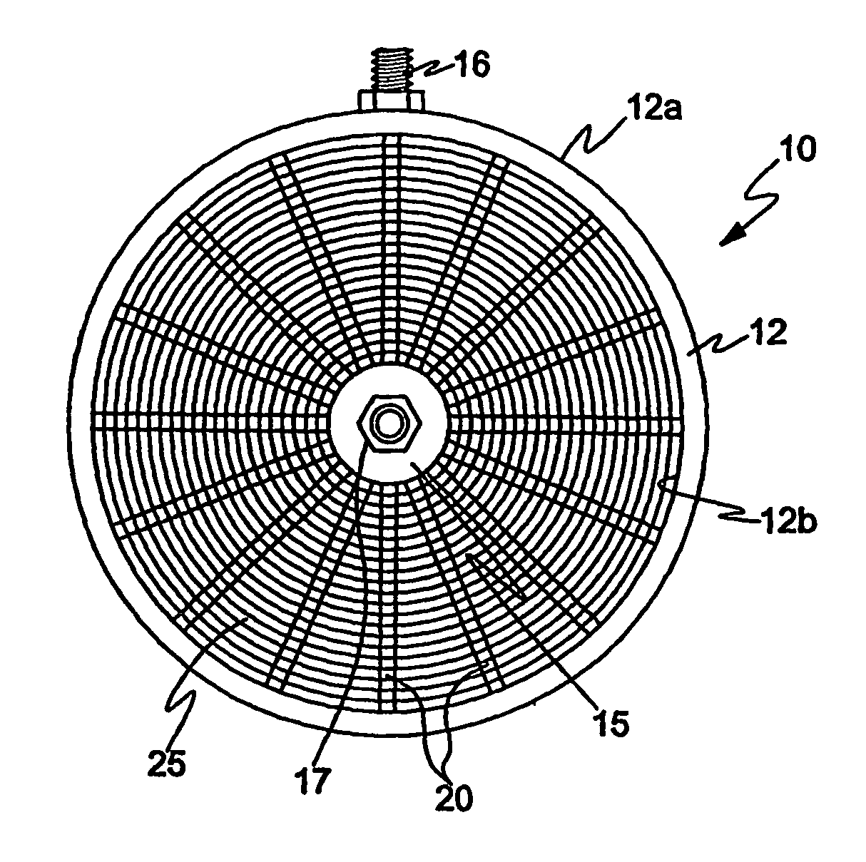
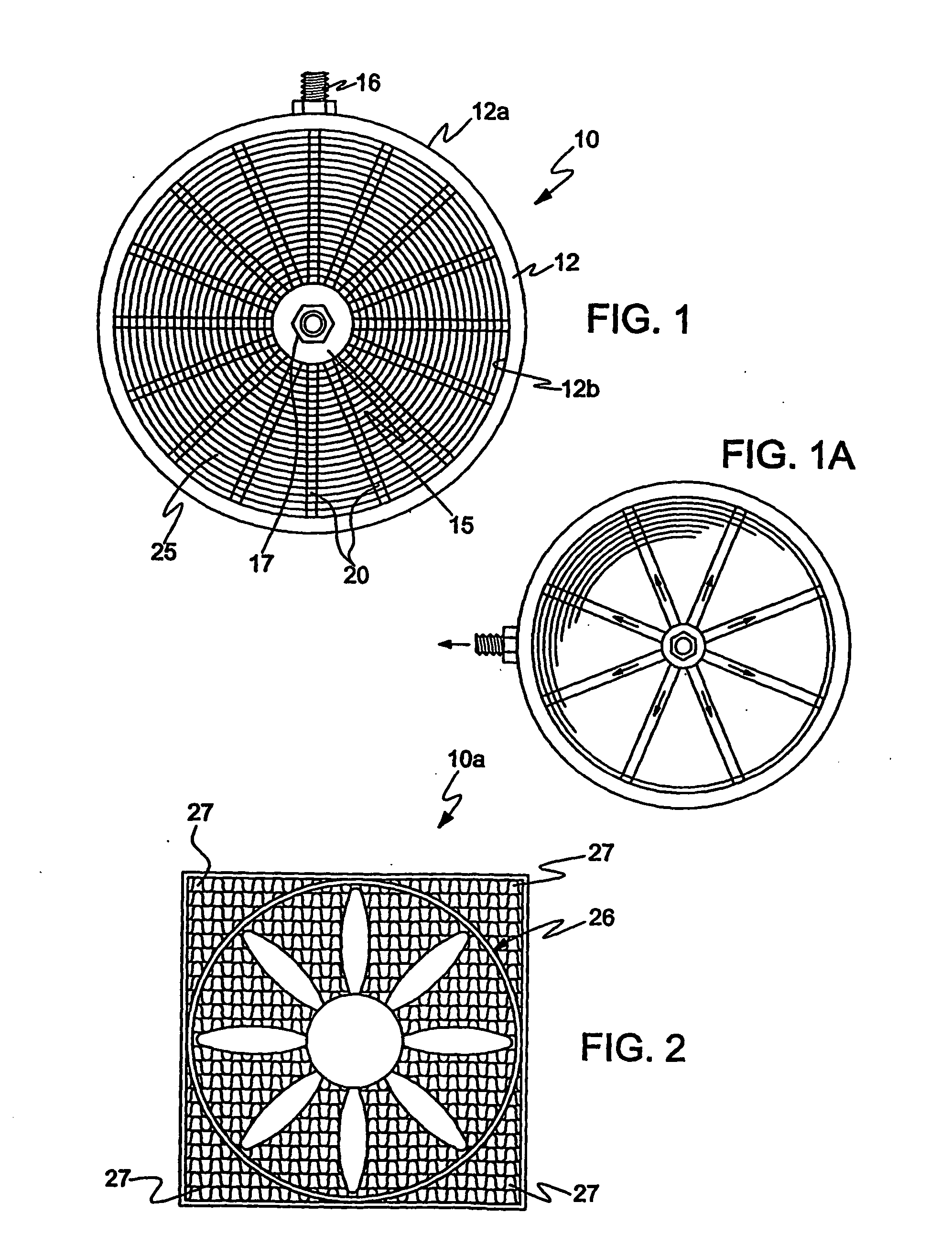
Referring to the drawings which illustrate a preferred form of the invention, FIG. 1 shows a radial flow heat exchanger 10 and which includes an outer fluid tight hollow ring 12 and a fluid tight central hub 15 disposed radially inwardly of the ring 12. For explanation purposes, a heat exchanger in which the flow is radially inward will be described, although it is understood that the flow could be radially outward as illustrated in FIG. 1a, the arrows indicating the direction of flow.

The ring 12, illustrated as generally circular, includes a fluid inlet fitting 16, sealed thereto, for introducing fluid into the hollow ring, the latter effectively forming a manifold. The inlet fitting may be brazed or welded to the ring. The ring itself may be circular in cross-section or polygonal, e.g., square, rectangular and the like, and composed of a thermally conductive material, preferably a metal. If desired, depending on the nature of the fluid, the ring and the other components of the ...


PUM

PropertyMeasurementUnit
heat conductingaaaaaaaaaa
flow lengthaaaaaaaaaa
lengthaaaaaaaaaa

Abstract

A radial flow heat exchanger for heating or cooling a fluid includes a sealed fluid manifold for passage of fluid. A sealed fluid receiving hub is spaced interiorly of the interior peripheral portion of the manifold and includes a passageway for passage of fluid into or out of the heat exchanger. A plurality of separate and spaced fluid flow tubes are disposed between the manifold and the hub. Each of the tubes are in sealed fluid communication with the manifold at one end and the other end is in sealed fluid communication with the hub. A fin assembly is positioned between the manifold and the hub and includes a heat conducting material arranged at spaced intervals between the manifold and the hub, the heat conducting material including a plurality of spaced apertures through which tubes pass. The heat conducting material is in intimate heat conducting contact with the tubes whereby fluid flowing between the manifold and the hub flows into each of the tubes in a radial direction between the manifold and the hub and wherein the heat conducting material of the fin assembly operates to give up or pick up heat from the fluid through the wall of the tubes.

Description

BACKGROUND OF THE INVENTION This invention relates to heat exchangers and more particularly to an improved radial flow heat exchanger in which the fluid to be heated or cooled flows between an outer peripheral portion of the heat exchanger, through a plurality of radially extending tubes, and a center hub, the tubes passing through a fin arrangement. Various types of heat exchangers are known such as shell in tube heat exchangers and radial flow heat exchangers. In the radial flow heat exchangers of the prior art, fluid flow tubes are arranged in a helical manner with the flow of fluid being in a spiral fashion through the helically formed tubes. Typical of the prior art patents related to radial flow heat exchangers are the following: Kissinger, U.S. Pat. No. 4,182,423 of 1980; Gilli et al, U.S. Pat. No. 3,712,370 of 1973; Tipman et al, U.S. Pat. No. 5,088,550 of 1992; Borjesson et al. U.S. Pat. No. 4,128,125 of 1978; Dobbins et al, U.S. Pat. No. 4,883,117 of 1989, by way of exam...

Claims


Application Information

Patent Timeline
Patent Type & Authority Applications(United States)
IPC IPC(8): F28D1/053F28F1/12F28F1/32F28F1/40F28F9/02F28F13/12F28F27/02
CPCF28D1/053F28D2001/0273F28F1/126F28F1/325Y10T29/4938F28F9/02F28F9/026F28F13/12Y10T29/49373F28F1/40
Inventor GREGORY, CHRISTIAN T.
Owner GREGORY CHRISTIAN T
Why Eureka
Try Eureka