
Cold cathode fluorescent lamps

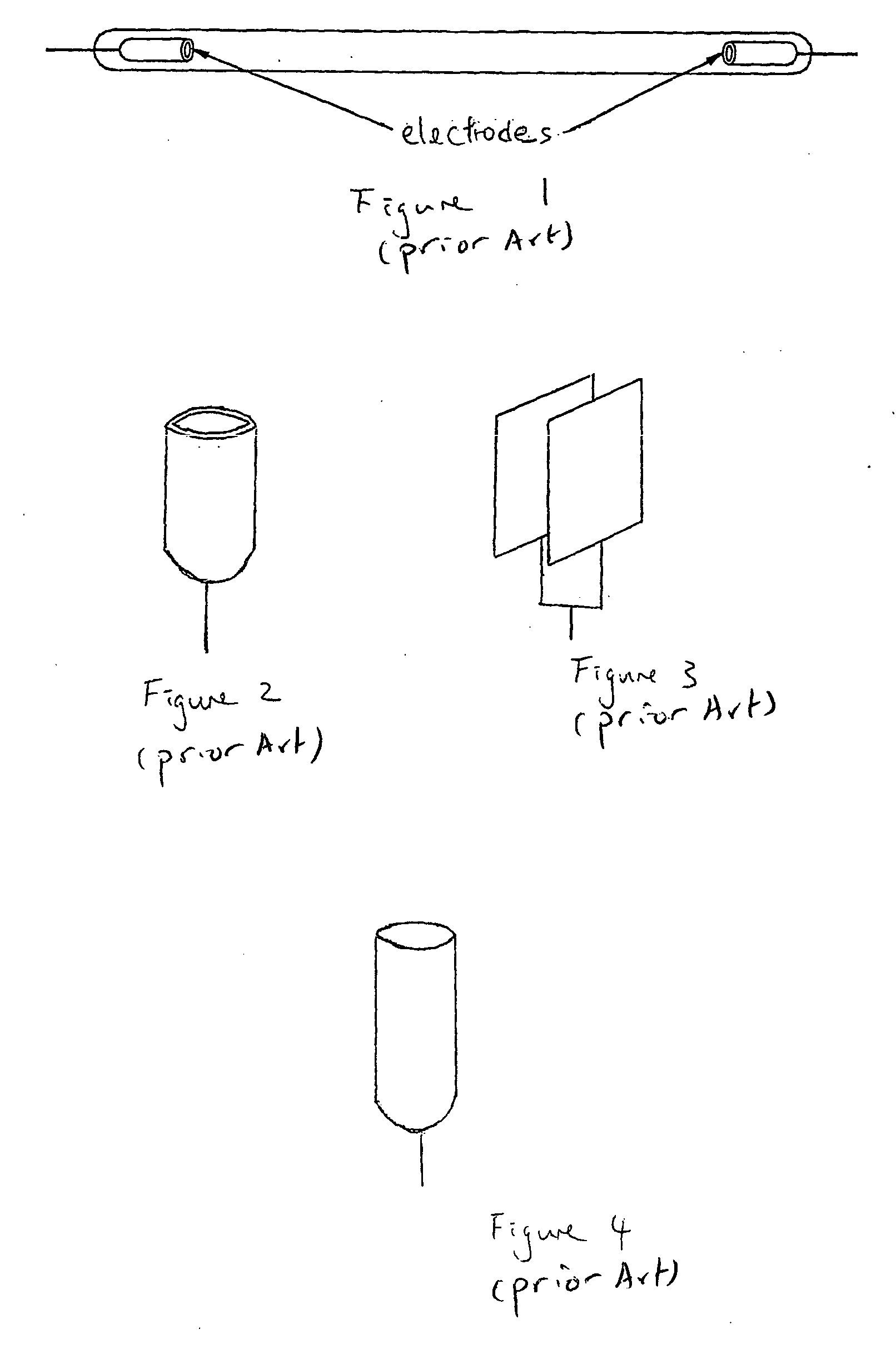
a technology of fluorescent lamps and cathode tubes, applied in the direction of discharge tubes, low-pressure discharge lamps, discharge tubes luminescnet screens, etc., can solve the problems of sputtering, electrodes are “deactivated” and lamps are no longer operational, so as to reduce and/or eliminate sputtering and improve the life of ccfl.

Inactive Publication Date: 2005-03-17
COLOR STARS
View PDF1 Cites 11 Cited by
  • Summary
  • Abstract
  • Description
  • Claims
  • Application Information

AI Technical Summary

Benefits of technology

[0010] It is therefore an object of the present invention to improve the lifetime of a CCFL by reducing and / or eliminating sputtering or to at least provide the public with a useful choice.
[0030] In a fourth aspect the present invention consists in a method of reducing sputter in a cold-cathode fluorescent lamp as described above wherein said electrode provided juxtaposed a region of said inner surface of the lighting tube

Problems solved by technology

During this period of bombardment a quantity of the emissive coating becomes sputtered away and by this mechanism upon successive starting and “glow to arc” transitions the emissive coating becomes consumed until after a successive number of starts there is no longer sufficient emissive coating to supply electrons to the discharge so that the electrode becomes “deactivated” and the lamp is no longer operational.
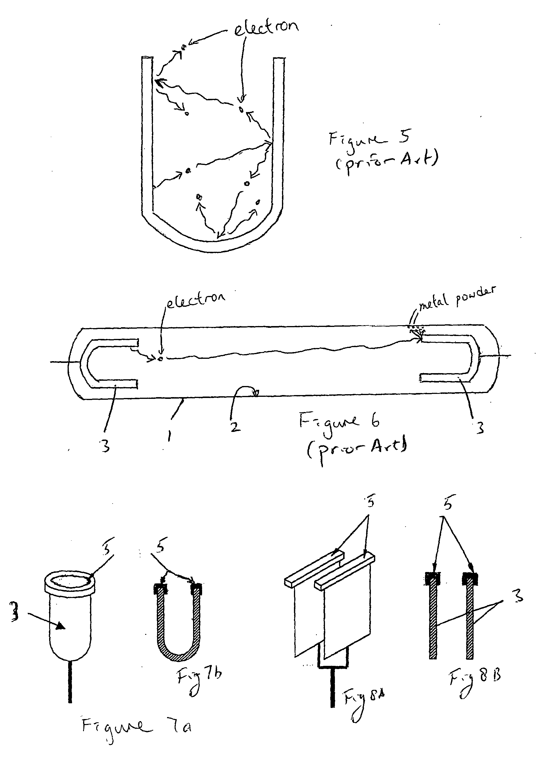
One problem with the current CCFL is that sputtering occurs when the electrons bombard a small surface area at the end of the electrode (cathode) farthest into the tube (FIG. 6).
One result of sputtering is that it causes metal to be collected on the fluorescent powder or the inner wall of the glass tube.
Sputtering will reduce the brightness of the lamp because of the metal “coating” on the wall.
The secondary conducting path may cause emission of waste gases from the glass and eventual breakage of the glass tube.

Method used


Image

  • Cold cathode fluorescent lamps
  • Cold cathode fluorescent lamps
  • Cold cathode fluorescent lamps

Examples


Embodiment Construction

[0061] One embodiment of the present invention involves the use of an electron shield or cap made of electrically insulating and heat resistant material, such as ceramic material, quartz, or enamel which is attached to the end of at least one of the electrodes (or to only the cathode if the lamp is driven by DC current). Since alternating current is commonly applied to the CCFL used (usually with a frequency in the range of 30 kHz to 100 kHz), both electrodes can be considered a “cathode”. The CCFL will normally consist of a sealed lighting tube 1 (preferably of 12 mm outside diameter or less) which has provided on at least part of its inwardly facing surface 2 a phosphorous material. Within the lighting tube (preferably of a cylindrical thin wall sectioned) will be provided at least one and preferably two electrodes as for example shown in FIG. 10. The electrodes 3 may themselves be substantially of a cylindrical shape as for example as shown in FIG. 7, or consist of parallel plate...


PUM


Abstract

A cold-cathode fluorescent lamp, comprising a sealed lighting enclosure provided with a phosphor coating on at least part of an inner surface thereof the lighting enclosure. An electrode is provided juxtaposed a region of the inner surface of the lighting tube, the electrode energisable from an external source of energy via an electric lead supporting the electrode, and positioned adjacent the main ionisation region within the lighting enclosure. The phosphor is to be excited by radiation to be generated inside the lighting tube by electric discharge from the electrode to provide visible radiation. At least part of the surface(s) of that portion of the electrode proximal most to the ionisation region are overlaid by a cap made from a high heat resistive and non conductive material.

Description

FIELD OF THE INVENTION [0001] The present invention relates to improvements to cold cathode fluorescent lamps. BACKGROUND TO THE INVENTION [0002] Cold Cathode Fluorescent Lamps (CCFL) generally comprise a tube containing an inert gas or a mixture of inert gases and a small quantity of mercury. A pair of complementary electrodes are sealed at opposite ends of the tube in order to supply electrical current through the tube, and a small quantity of an electron emissive material is coated on the surface of the electrodes in order to promote the emission of electrons. When a sufficiently high voltage is applied across the lamps, by means of the electrodes, the electric field established causes some of the electrons within the inert gas and mercury vapour to become accelerated in the direction of the electrodes. Some of the electrons and ions thereby created reach the electrodes with sufficient kinetic energy to cause the electrodes to become heated to emit more electrons partially by the...

Claims


Application Information

Patent Timeline
Patent Type & Authority Applications(United States)
IPC IPC(8): H01J61/04H01J61/067H01J61/10
CPCH01J61/04H01J61/10H01J61/09H01J61/78H01J61/067
Inventor CHOW, LAP LEECHOW, LAP HANG
Owner COLOR STARS
Learn More