Converter circuit and motor driving apparatus

a converter circuit and motor technology, applied in the direction of instant pulse delivery arrangement, electric power transfer ac network, conversion with intermediate conversion to dc, etc., can solve the problems of capacitor b>17/b> not being able to reduce the size of the motor driving apparatus including these circuits, and the capacitor b>17/b> cannot be reduced by a predetermined value or more, so as to reduce the size and cost of the refrigerator, reduce the size and cost, and reduce the capacitor capacitor

Inactive Publication Date: 2005-03-17
PANASONIC CORP
View PDF6 Cites 74 Cited by
  • Summary
  • Abstract
  • Description
  • Claims
  • Application Information

AI Technical Summary

Benefits of technology

[0052] According to a thirtieth aspect of the present invention, an air conditioner receiving a voltage from an AC power supply and having a compressor comprises a motor driving apparatus for driving a motor of the compressor; and the motor driving apparatus being a motor driving apparatus according to the seventh aspect of the present invention. Therefore, the capacitances of the capacitors used in the converter circuit of the motor driving apparatus can be reduced, whereby the motor driving apparatus is reduced in size and cost, leading to reductions in size and cost of the refrigerator.
[0053] According to a thirty-first aspect of the present invention, a refrigerator receiving a voltage from an AC power supply and having a compressor comprises a motor driving apparatus for driving a motor of the compressor; and the motor driving apparatus is a motor driving apparatus according to the seventh aspect of the present invention. Therefore, the capacitances of the capacitors used in the converter circuit of the motor driving apparatus can be reduced, whereby the motor driving apparatus is reduced in size and cost, leading to reductions in size and cost of the compressor.
[0054] According to a thirty-second aspect of the present invention, an electric washing machine receiving a voltage from an AC power supply comprises a motor; a motor driving apparatus for driving a motor of the compressor; and the motor driving apparatus is a motor driving apparatus according to the seventh aspect of the present invention. Therefore, the capacitances of the capacitors used in the converter circuit of the motor driving apparatus can be reduced, whereby the motor driving apparatus is reduced in size and co

Problems solved by technology

Further, if the capacitance of the voltage-doubler capacitor is small, the capacitor does not operate as a voltage-doubler capacitor.
However, considering the efficiency of the voltage conversion circuit 11 or the cost of the harmonic switching element, there is a limitation in actuall

Method used


Image

  • Converter circuit and motor driving apparatus
  • Converter circuit and motor driving apparatus
  • Converter circuit and motor driving apparatus

Examples


embodiment 1

[0075] [Embodiment 1]

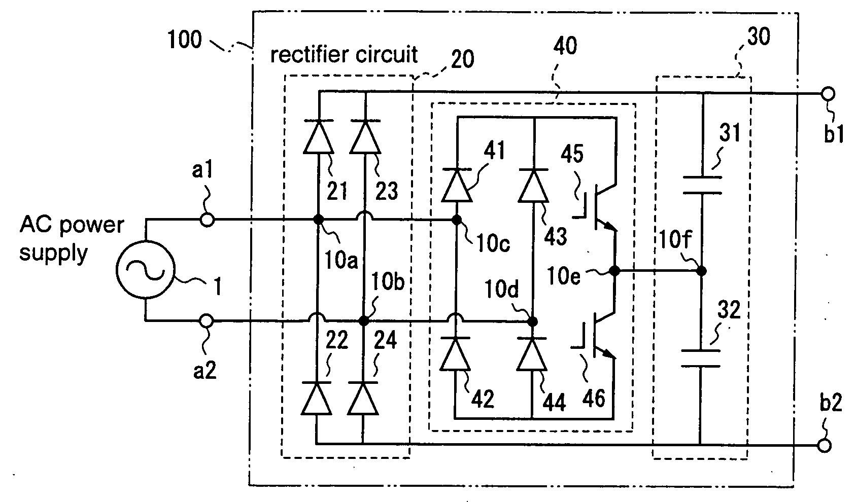
[0076]FIG. 1 is a diagram for explaining a converter circuit according to a first embodiment of the present invention.

[0077] The converter circuit 100 according to the first embodiment receives an AC voltage supplied from an AC power supply 1, and converts the input voltage into a non-negative voltage that is equal to or larger than the amplitude of the input voltage. The converter circuit 100 has a pair of input terminals a1 and a2 to which the output voltage of the AC power supply 1 is applied, and a pair of output terminals b1 and b2 from which the non-negative voltage equal to or larger than the amplitude of the input voltage is output.

[0078] To be specific, the converter circuit 100 comprises a rectifier circuit 20 for rectifying the output voltage of the AC power supply 1, which is applied to the input terminals a1 and a2; first and second capacitors 31 and 32 which are connected in series between the output terminals b1 and b2; and a switch circuit 40 f...

embodiment 2

[0101] [Embodiment 2]

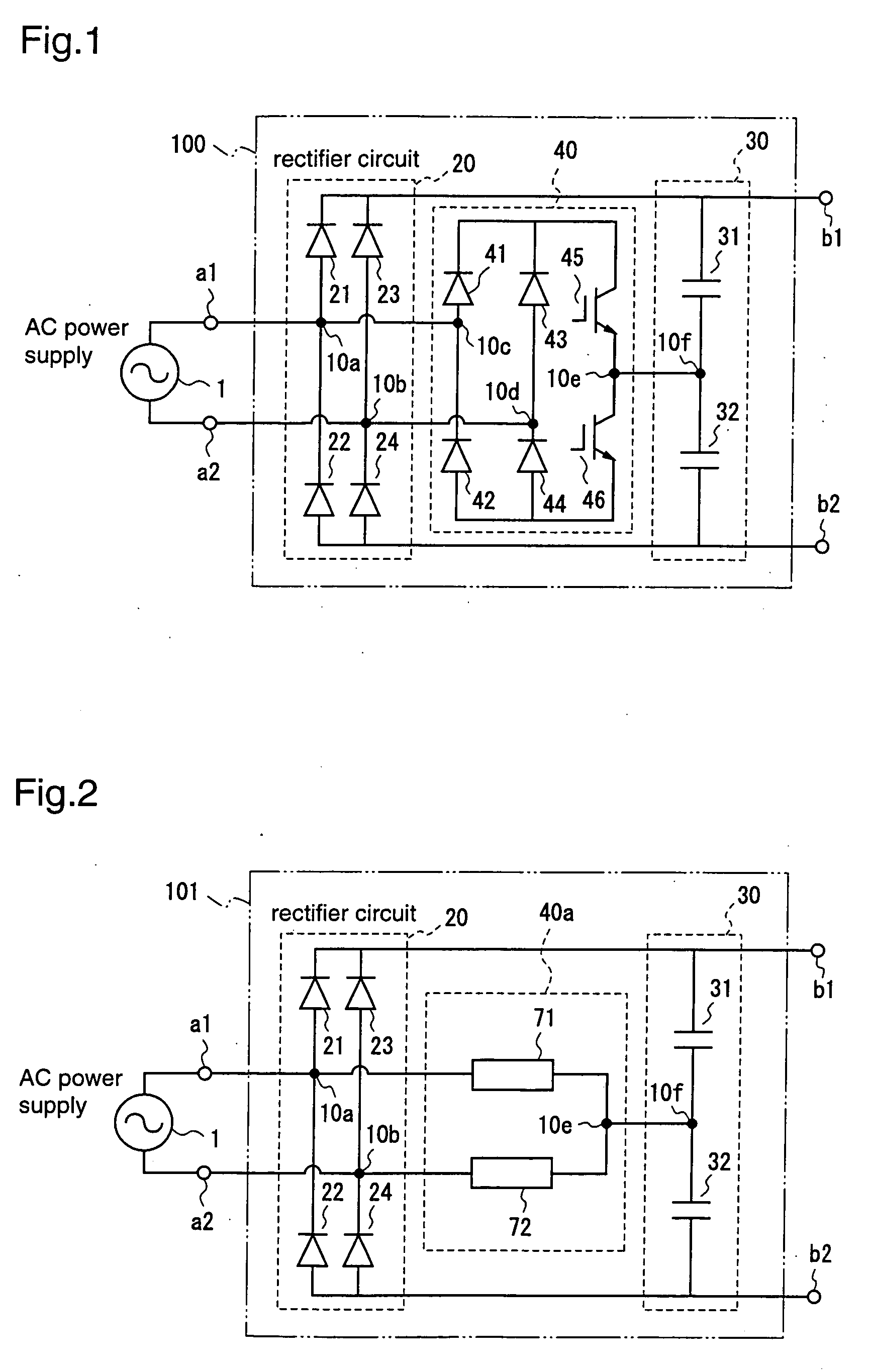
[0102]FIG. 2 is a block diagram for explaining a converter circuit according to a second embodiment of the present invention.

[0103] The converter circuit 101 according to the second embodiment boosts the output voltage of the AC power supply 1 like the converter circuit 100 according to the first embodiment, and it is composed of a rectifier circuit 20, a capacitor circuit 30, and a switch circuit 40a.

[0104] The rectifier circuit 20 and the capacitor circuit 30 are identical to those of the first embodiment. The switch circuit 40a comprises a first bidirectional switching element 71 which is connected between the input terminal a1 of the converter circuit 101 and the connection node 10f of the capacitor circuit 30, and a second bidirectional switching element 72 which is connected between the input terminal a2 of the converter circuit 101 and the connection node 10f of the capacitor circuit 30.

[0105] In the switch circuit 40a, on-off of the first and second b...

embodiment 3

[0116] [Embodiment 3]

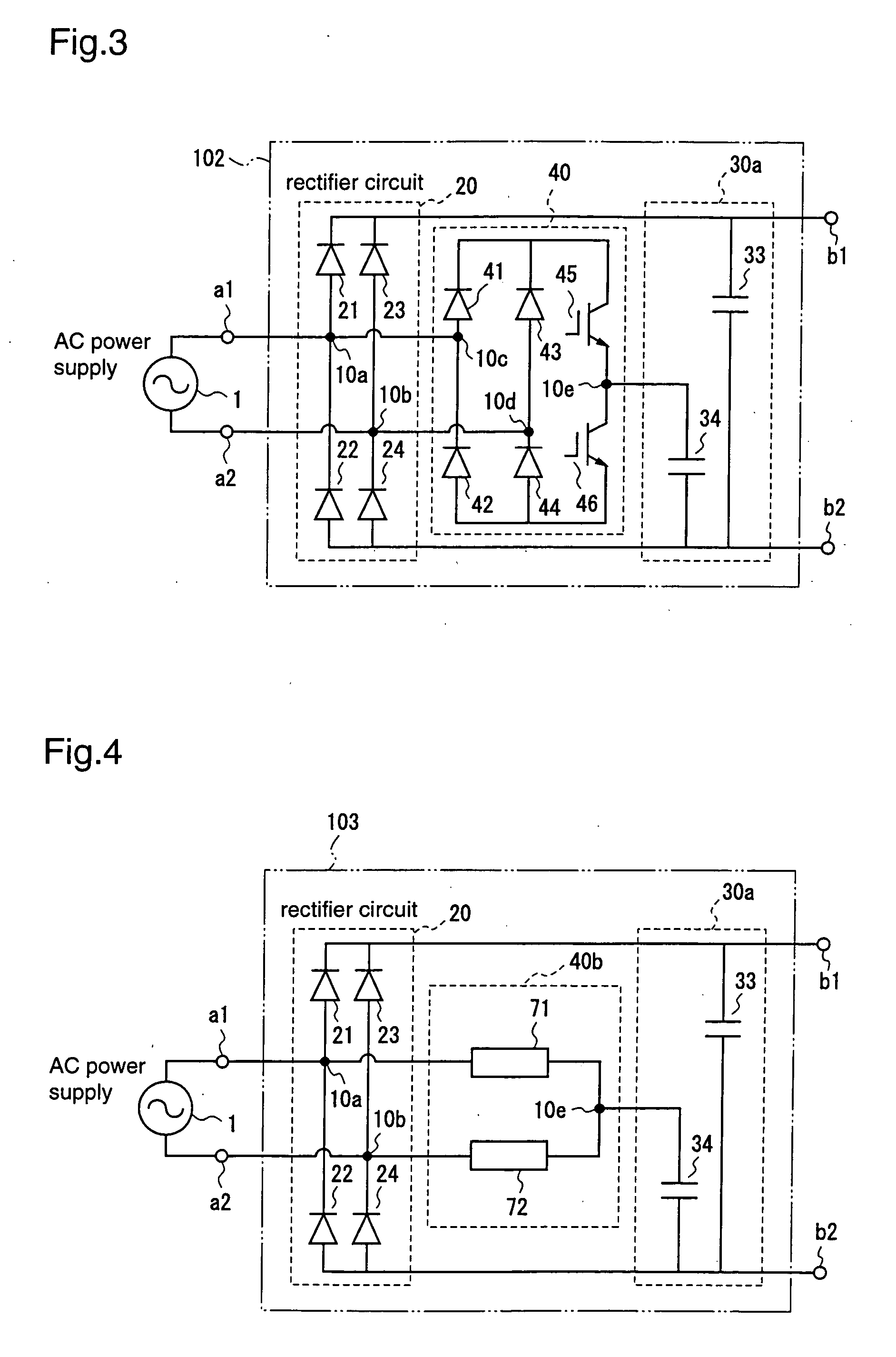
[0117]FIG. 3 is a diagram for explaining a converter circuit according to a third embodiment of the present invention.

[0118] The converter circuit 102 according to the third embodiment boosts the output voltage of the AC power supply 1 like the converter circuit 100 according to the first embodiment, and it is composed of a rectifier circuit 20, a capacitor circuit 30a, and a switch circuit 40.

[0119] The rectifier circuit 20 and the switch circuit 40 are identical to those of the first embodiment. The capacitor circuit 30a comprises a third capacitor 33 connected between the output terminals b1 and b2, and a fourth capacitor 34 connected between the output terminal b2 and the connection node 10e of the first and second switching elements of the switch circuit 40. While the capacitor circuit 30a comprises the two capacitors 33 and 34, it may comprise third and fourth capacitor units each comprising plural capacitors connected, instead of the third and fourth ca...


PUM


Abstract

A converter circuit for converting an output voltage from an AC power supply is provided with a rectifier circuit for rectifying the output voltage of the AC power supply; first and second capacitors connected in series, for smoothing the output of the rectifier circuit; and a switch circuit for switching the connections between the respective capacitors and the AC power supply so that the output voltage of the AC power supply is applied to each of the respective capacitors at a cycle shorter than the cycle of the AC power supply.

Description

FIELD OF THE INVENTION [0001] The present invention relates to a converter circuit and a motor driving apparatus and, more particularly, to a converter circuit capable of boosting an input voltage, and a motor driving apparatus using the converter circuit. BACKGROUND OF THE INVENTION [0002] Conventionally, a full-wave voltage doubler circuit has been employed to boost an input voltage from 100V to 200V. [0003]FIG. 16 is a diagram illustrating an example of a conventional full-wave voltage doubler circuit. [0004] The full-wave voltage doubler circuit 10 comprises a bridge diode circuit 4 for rectifying an output voltage of an AC power supply 1, a power-factor improvement reactor 3 which is connected in series between the AC power supply 1 and the bridge diode circuit 4, two electrolytic capacitors 5 and 6 which are connected in series to each other and in parallel to the bridge diode circuit 4, and an electrolytic capacitor 9 which is connected in parallel to the electrolytic capacit...

Claims


Application Information

Patent Timeline
IPC IPC(8): H02M7/06H02M7/12H02M7/10H02P7/00H02P29/00H03K5/153
CPCH02M5/458H02M7/06H02M7/10
Inventor UEDA, MITSUONAKATA, HIDEKIOGAWA, MASANORI
Owner PANASONIC CORP
Why Eureka
Try Eureka