Current driver and display device

a display device and driver technology, applied in static indicating devices, instruments, electroluminescent light sources, etc., can solve the problem that the human eye perceives the brightness as nonlinear, and achieve the effect of improving the resolution of the display device and correcting the display characteristics

Inactive Publication Date: 2005-03-17
GK BRIDGE 1
View PDF10 Cites 20 Cited by
  • Summary
  • Abstract
  • Description
  • Claims
  • Application Information

AI Technical Summary

Benefits of technology

The current divider circuit includes: a first current input MISFET of first conductivity type which is connected to the first variable current source, the gate electrode and drain of the first current input MISFET being connected to each other; a first current distribution MISFET of first conductivity type, the first current distribution MISFET and the first current input MISFET constituting a current mirror; a second current input MISFET of first conductivity type which is connected to the second variable current source, the gate electrode and drain of the second current input MISFET being connected to each other; a second current distribution MISFET of first conductivity type, the second current distribution MISFET and the second current input MISFET constituting a current mirror; a third current input MISFET of second conductivity type which is connected to the drain of the second current distribution MISFET, the gate electrode and drain of the third current input MISFET being connected to each other; a fourth current input MISFET of second conductivity type which is connected to the drain of the first current distribution MISFET, the gate electrode and drain of the fourth current input MISFET being connected to each other; a first MISFET having a drain which is connected to the drain of the first current distribution MISFET and a source of the fourth current input MISFET, the first MISFET and the third current input MISFET constituting a current mirror having a mirror ratio of 1; a plurality of current source MISFETs, the current source MISFETs and the fourth current input MISFET constituting current mirrors, the mirror ratio of each current source MISFET to the fourth current input MISFET being 1 / m where in is a natural number equal to or greater than 2. With such a structure, the difference between the first reference current and the second reference current is divided into equal parts with high accuracy using a current mirror. Thus, when a current driver including the above current divider circuit is used in a display device, it is possible to increase the brightness according to the increase of the grayscale value, for example. Further, a large difference in the brightness is prevented from being caused at the grayscale value at the boundaries between the sub-ranges of grayscale values. It should be noted that, with the above structure, the number of transistors is significantly decreased as compared with a conventional current driver, and accordingly, the circuit area is smaller than that of the conventional current driver. Therefore, the size of the current source MISFETs is increased, and a variation among output currents is reduced.
The grayscale values of the image data are included in any of a low grayscale range, a middle grayscale range, and a high grayscale range. The difference in the current value between the first reference current and the second reference current which is obtained when the grayscale value of the image data is in the low grayscale range or the high grayscale range is smaller than the difference in the current value between the first reference current and the second reference current which is obtained when the grayscale value of the image data is in the middle grayscale range. With such a structure, the output current is specifically corrected according to the visual characteristics of a human eye. Therefore, a user visually perceives images more correctly.
The current driver further comprises a plurality of resistive elements which are connected in series between a supply voltage supplying section and a ground, wherein each of the plurality of voltage supplying sections is a node between adjoining resistive elements of the plurality of resistive elements. With such a structure, it is possible to readily correct the output current by arbitrarily setting the resistance values of the resistive elements. In the case where the number of the resistive elements is equal to the number of outputs plus 1, the output current can be corrected for each grayscale value. Thus, display can be performed with more accuracy.

Problems solved by technology

The present inventors examined the causes of failure to perform display with brightness fidelity to image data and found that the way a human eye perceives the brightness is nonlinear and this is the cause of such failure.

Method used


Image

  • Current driver and display device
  • Current driver and display device
  • Current driver and display device

Examples


embodiment 1

(Embodiment 1)

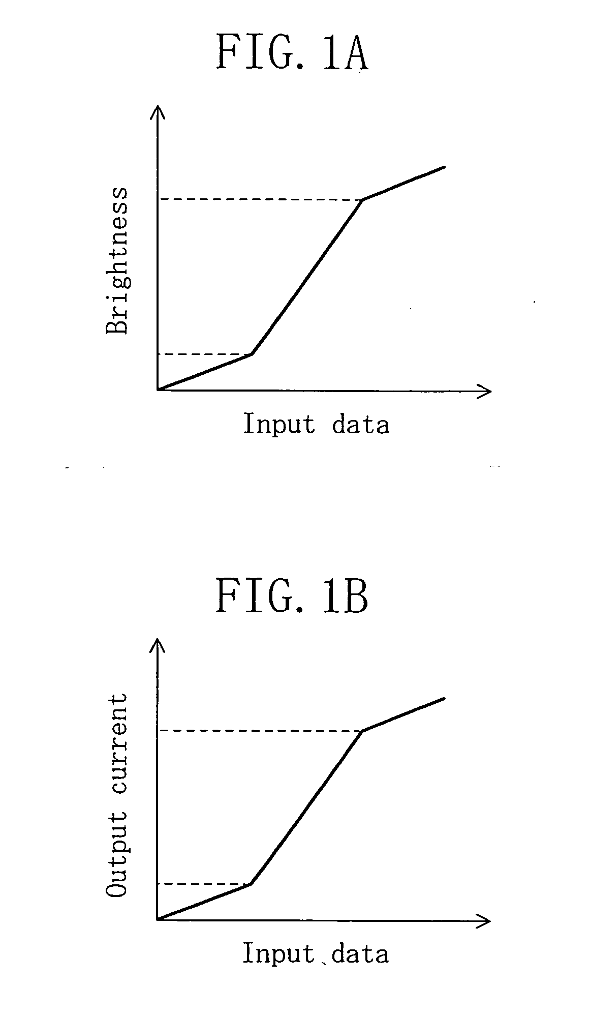
FIG. 1A illustrates the relationship between the grayscale value of input data and the display brightness in an organic EL display device according to embodiment 1 of the present invention. FIG. 1B illustrates the relationship between the grayscale value of input data and the output current in a current driver according to embodiment 1.

In the example shown in FIG. 1A, the display brightness of the organic EL display device is divided into three brightness ranges according to the grayscale value of input data (image data). The gradient of the graph which represents the relationship between the brightness and the grayscale vale of input data is different among the brightness ranges. In the example shown in FIG. 1A, we refer to the low brightness range, the middle brightness range and the high brightness range as the first range, the second range and the third range, respectively. The gradient of the graph is steeper in the second range than in the first and third range...

embodiment 2

Variation of Embodiment 2

FIG. 11 is a circuit diagram showing a variation of the current driver of embodiment 2.

The variation described herein is different from the above-described structure of embodiment 2 in that the conductivity type of the third MISFET 11 which receives the output of the operational amplifier 9 at the gate electrode is changed to n-channel type. Thus, the voltage selection circuit 7, the resistive elements R0 to Rn and the switches SWc0 to SWcn−1 are the same as those of the above-described current driver of embodiment 2. Hereinafter, only the differences from the above-described current driver of embodiment 2 are described.

The current driver of the variation of embodiment 2 includes: an output resistor 23; a sixth MISFET 19 of p-channel type; a seventh MISFET 21 of p-channel type; a fourth MISFET 13 of n-channel type which is connected to the seventh MISFET 21; and a fifth MISFET 15 of n-channel type. One end of the output resistor 23 is connected to the so...


PUM


Abstract

A current driver to which image data including a plurality of grayscale values is input and which outputs an electric current according to the grayscale values of the image data, the current driver comprising: a first input section to which a first reference current is input, a current value of the first reference current being changed according to the grayscale values of the image data; a second input section to which a second reference current is input, the second reference current having a current value different from that of the first reference current; and a current divider circuit which uses the second reference current and the first reference current to output an electric current, the electric current having a value equal to or higher than that of the first reference current and equal to or lower than that of the second reference current.

Description

BACKGROUND OF THE INVENTION 1. Field of the Invention The present invention relates to a current driver for supplying a drive current to a display panel, such as an organic EL (Electro Luminescence) display device, or the like. 2. Description of the Prior Art An organic EL element is an element which itself emits light according to the magnitude of en electric current input to the element. An organic EL display device including organic EL elements over a panel requires no backlight, and accordingly, the thickness thereof can be reduced. Further, the organic EL display device has no limitation on the viewing angle. Thus, the organic EL display device has been an expected next-generation display device which can replace liquid crystal display devices. Among various organic EL display devices, an active organic EL display device, including TFTs (thin film transistors) and organic EL elements which are provided to pixels arranged in a matrix, for example, over a panel on a one-to-on...

Claims


Application Information

Patent Timeline
Patent Type & Authority Applications(United States)
IPC IPC(8): G09G3/10G09G3/20H01L51/50G09G3/30G09G3/32H05B33/14
CPCG09G3/3283G09G2320/0276G09G2310/027G09G3/30
Inventor DATE, YOSHITO
Owner GK BRIDGE 1
Why Eureka
Try Eureka