
Wide-angle zoom lens including at least one aspheric lens surface
a wide-angle zoom and lens technology, applied in the field of wide-angle zoom lenses including at least one aspheric lens surface, can solve the problems of difficult to simulate a picture taken at a wide-angle from an image taken at the telephoto end, difficult to satisfy the demands of compactness, unacceptable optical performance, etc., to achieve excellent correction of lateral color aberration, distortion, and image surface curvatur
- Summary
- Abstract
- Description
- Claims
- Application Information
AI Technical Summary
Benefits of technology
Problems solved by technology
Method used
Image

Examples
embodiment 1
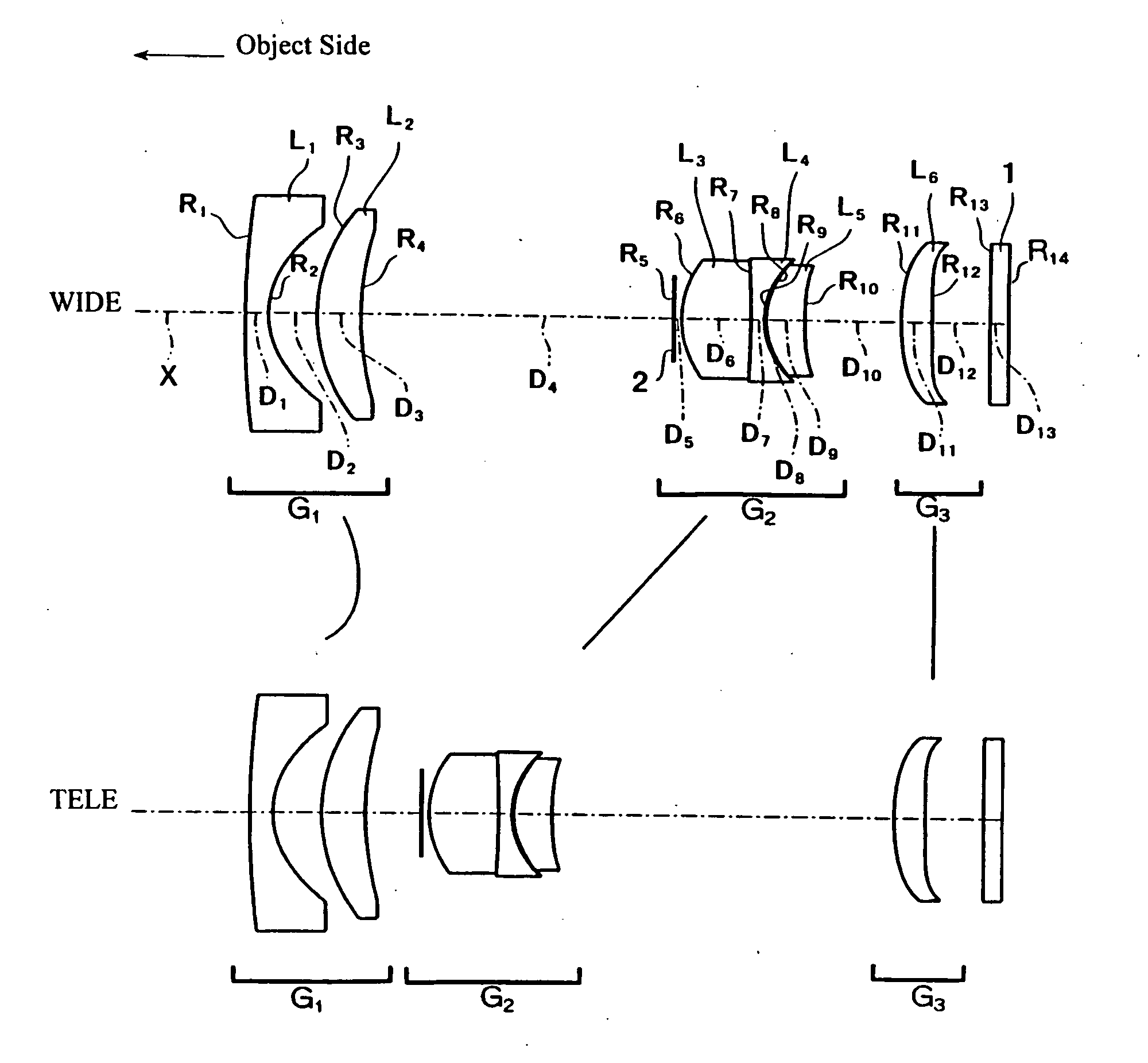
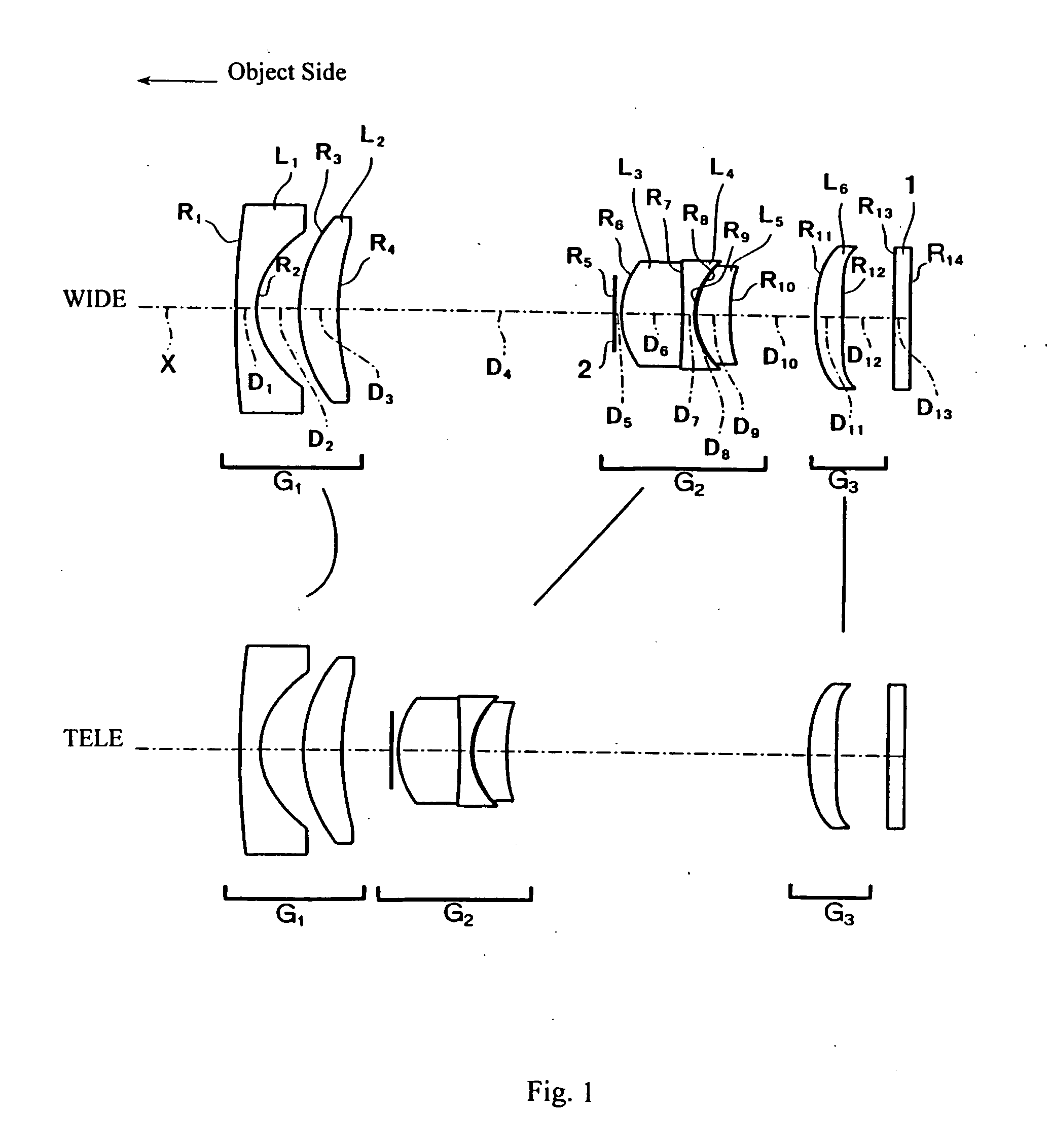
In Embodiment 1, as shown in FIG. 1, the first lens group G1 is formed of, in order from the object side, a first lens element L1 of negative refractive power that is nearly piano-concave but with a meniscus shape and with a concave surface on the image side, and a second lens element L2 of positive refractive power and a meniscus shape with its object-side surface being convex. Both surfaces of lens element L1 are aspheric surfaces with the aspheric surface shapes expressed by Equation (A) above including both even-order and odd-order, non-zero terms due to both even-order and odd-order aspheric coefficients Ai being non-zero.
The second lens group G2 is formed of, in order from the object side, the stop 2, a lens component formed of, in order from the object side, a third lens element L3 that is a biconvex lens element with its object-side surface having a greater curvature (i.e., a smaller radius of curvature) than its image-side surface and that is joined, such as by being cem...
embodiment 2
Embodiment 2 is shown in FIG. 3. Embodiment 2 is similar to Embodiment 1 and therefore only the differences between Embodiment 2 and Embodiment 1 will be explained. Embodiment 2 differs from Embodiment 1 in that in Embodiment 2, the sixth lens element L6 is a meniscus lens element with its convex surface on the image side. Also, Embodiment 2 differs from Embodiment 1 in its lens element configuration by different radii of curvature of lens surfaces, different aspheric coefficients of the aspheric lens surfaces, different optical element surface spacings, and one different refractive material.
Table 5 below lists numerical values of lens data for Embodiment 2. Table 5 lists the surface number #, in order from the object side, the radius of curvature R (in mm) of each surface on the optical axis, the on-axis surface spacing D (in mm) between surfaces, as well as the refractive index Nd and the Abbe number νd (at the d-line of 587.6 nm) of each optical element for Embodiment 2. Liste...
PUM
 Abstract
Description
Claims
Application Information