Video protection circuit providing short to battery protection while maintaining termination impedance

Active Publication Date: 2005-03-17
VISTEON GLOBAL TECH INC
View PDF15 Cites 4 Cited by
  • Summary
  • Abstract
  • Description
  • Claims
  • Application Information

AI Technical Summary

Benefits of technology

[0003] In satisfying the above need, as well as overcoming the enumerated drawbacks and other limitations of the related art, the present invention provides for a transistor in series with the video input of a video input device prior to the termination resistor. The transistor is utilized due to the large amount of power that would be dissipated across the termination resistor if the video input was inadvertently connected to the automotive battery voltage. For the typical automotive battery of 14 volts, approximately 2.6 watts would be dissipated by the termination resistor likely causing a failure of the termination resistor and the video input device. An N channel MOSFET is used as a switch to provide an extremely low series resistance compared to the 75 ohm termination resistor. This low series resistance minimizes video signal degradation which would be caused by higher impedance switches due to the voltage divider formed by the switch impedance and the 75 ohm termination resistor. The N channel MOSFET also provides fast switching speeds and can be selected to minimize parasitic capacitances such that the video signal is not degraded due to the 75 ohm source impedance.

Problems solved by technology

For the typical automotive battery of 14 volts, approximately 2.6 watts would be dissipated by the termination resistor likely causing a failure of the termination resistor and the video input device.

Method used


Image

  • Video protection circuit providing short to battery protection while maintaining termination impedance
  • Video protection circuit providing short to battery protection while maintaining termination impedance
  • Video protection circuit providing short to battery protection while maintaining termination impedance

Examples


Embodiment Construction

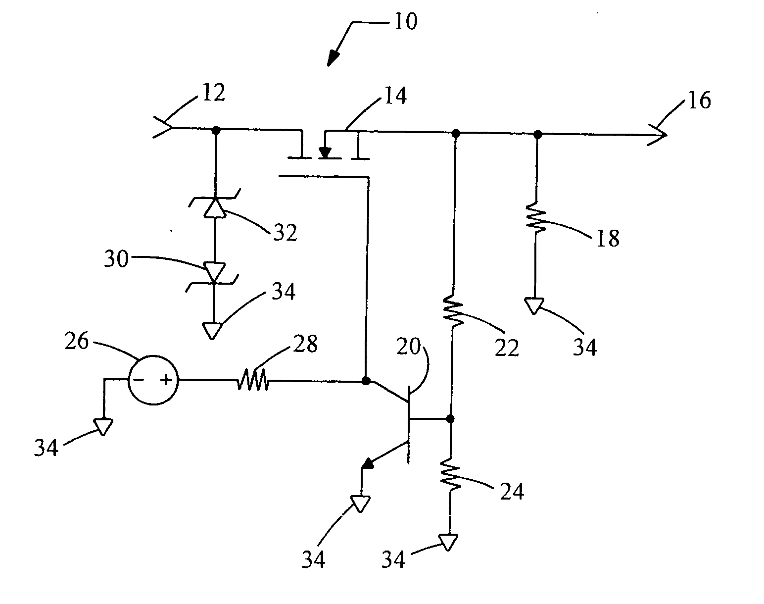
[0007] Referring now to FIG. 1, a video protection circuit embodying the principles of the present invention is illustrated therein and designated at 10. As its primary components, the video protection circuit 10 includes a video input terminal 12, a transistor 14, and a termination resistor 18.

[0008] The video input terminal 12 receives a video signal from a video output device (not shown). The transistor 14, selectively connects the video input terminal 12 with the video circuit 16. The video input terminal 12 is connected to the drain of transistor 14. The source of transistor 14 is connected to both termination resistor 18 and a video circuit 16.

[0009] During normal operation transistor 14 connects the video input terminal 12 with the video circuit 16 and the termination resistor 18. Alternatively, if the video input terminal 12 were to be shorted to the automotive battery (not shown), the impedance of transistor 14 is increased to point where the maximum current allowed throu...


PUM


Abstract

The present invention provides for a transistor in series with the video input of a video input device prior to the termination resistor. The transistor is utilized due to the large amount of power that would be dissipated across the termination resistor if the video input was inadvertently connected to the automotive battery voltage. For the typical automotive battery of 14 volts, approximately 2.6 watts would be dissipated over the termination resistor likely causing a failure in the video input device. An N channel MOSFET can be used as the switch to provide an extremely low series resistance compared to the 75 ohm termination resistor. This low series resistance minimizes video signal degradation which would be caused by higher impedance switches due to the voltage divider formed by the switch impedance and the 75 ohm termination resistor. An N channel MOSFET also provides fast switching speeds and can be selected to minimize parasitic capacitances such that the video signal is not degraded due to the 75 ohm source impedance.

Description

BACKGROUND OF THE INVENTION [0001] It is well known in the art of video transmission to use a terminator at the video input device to match the cable impedance thereby reducing electromagnetic interference and signal reflections to improve signal quality. Most composite video cable connections match a 75 ohm impedance cable with a 75 ohm termination resistor in the video input device. [0002] However, a need exists to protect the circuitry of the video input device in the case where an unexpectedly high voltage is connected to the video input circuit. This protection is particularly important in automotive applications where the video input can be inadvertently connected to the automotive battery causing a large amount of power to be dissipated across the termination resistor. Typically, systems utilize a DC blocking capacitor in series with the video input. The DC blocking capacitor has the disadvantage of causing a poor low frequency response which results in either a loss of synch...

Claims


Application Information

Patent Timeline
IPC IPC(8): H02H3/20H02H3/50H02H9/04H03F1/52H04N5/44
CPCH03F1/52
Inventor WEINDORF, PAUL F.L.LEINONEN, MARK A.
Owner VISTEON GLOBAL TECH INC
Why Eureka
Try Eureka