Frame structure for an adaptive modulation wireless communication system

a wireless communication system and frame structure technology, applied in the field of communication systems, can solve the problems of channel interference between adjacent adjacents, limited maximum bit per symbol rate modulation scheme that may be employed with a cell, and common distortion of signals

Inactive Publication Date: 2005-03-17
WI LAN INC
View PDF22 Cites 74 Cited by
  • Summary
  • Abstract
  • Description
  • Claims
  • Application Information

AI Technical Summary

Benefits of technology

[0016] The present invention also includes a method for determining the modulation scheme of a frame having a plurality of downlink time slots where one of the plurality of downlink slots contains control information. In this method the modulation scheme employed to generate the modulated data for the plurality of downlink time slots may vary for each of the plurality of downlink slots. In addition, the frame may be transmitted to a plurality of units where each of the plurality of units may support a modulation scheme having a maximum complexity. This method first determines the lowest modulation complexity supported by each of the plurality of units. Then the method sets the modulation complexity of the downlink slot of the plurality of downlink slots that contains control information to the determined lowest modulation complexity.
[0017] In this method, the downlink slot of the plurality of downlink slots that contains control information may be the first downlink slot in time order of the plurality of downlink slots. In addition, the method may also determine the complexity of the modulation scheme employed to generate the modulated data for at least two units of the plurality of units. Then the method may assign at least two time slots of the plurality of time slots to the at least two units based on the complexity of the modulation scheme employed to generate the modulated data for the at least two units. The assignment to the at least two units may be from the least complex modulation scheme to the most complex modulation scheme.

Problems solved by technology

The maximum bit per symbol rate modulation scheme that may be employed with a cell may be limited due to channel interference and the implementation or modem complexity of CPEs within the cell.
Channel interference may occur between adjacent time slots assigned to different CPEs within a cell due to distortion of signals between the base station in the cell and the CPEs.
The signals are commonly distorted by destructive multi-path replication of the signals (where the signals are reflected off physical objects in the cell).
In addition, the signals are commonly distorted by atmospheric conditions (such as rain).
It is noted, however, that the channel interference between CPEs and a base station varies for each CPE, e.g., as a function of the physical barriers between the base station and the CPE.
In addition, the implementation or modem complexity of the CPEs associated with the base station may also vary where some CPEs may be able to support higher bit per symbol rate modulation schemes than others associated with the base station.
Accordingly, the selection of one low bit per symbol rate modulation scheme for all CPEs where some CPEs may support a higher bit per symbol rate modulation in a cell may not maximize bandwidth utilization.
Unfortunately, variable bit per symbol rate modulation is not used for communication between base stations and associated CPEs due to its complexity.
In particular, variable bit per symbol rate modulation schemes normally require complex CPE demodulators where some CPEs may already have limited implementation or modem complexity.

Method used


Image

  • Frame structure for an adaptive modulation wireless communication system
  • Frame structure for an adaptive modulation wireless communication system
  • Frame structure for an adaptive modulation wireless communication system

Examples


Embodiment Construction

[0029] Throughout this description, the preferred embodiment and examples shown should be considered as exemplars, rather than as limitations on the present invention.

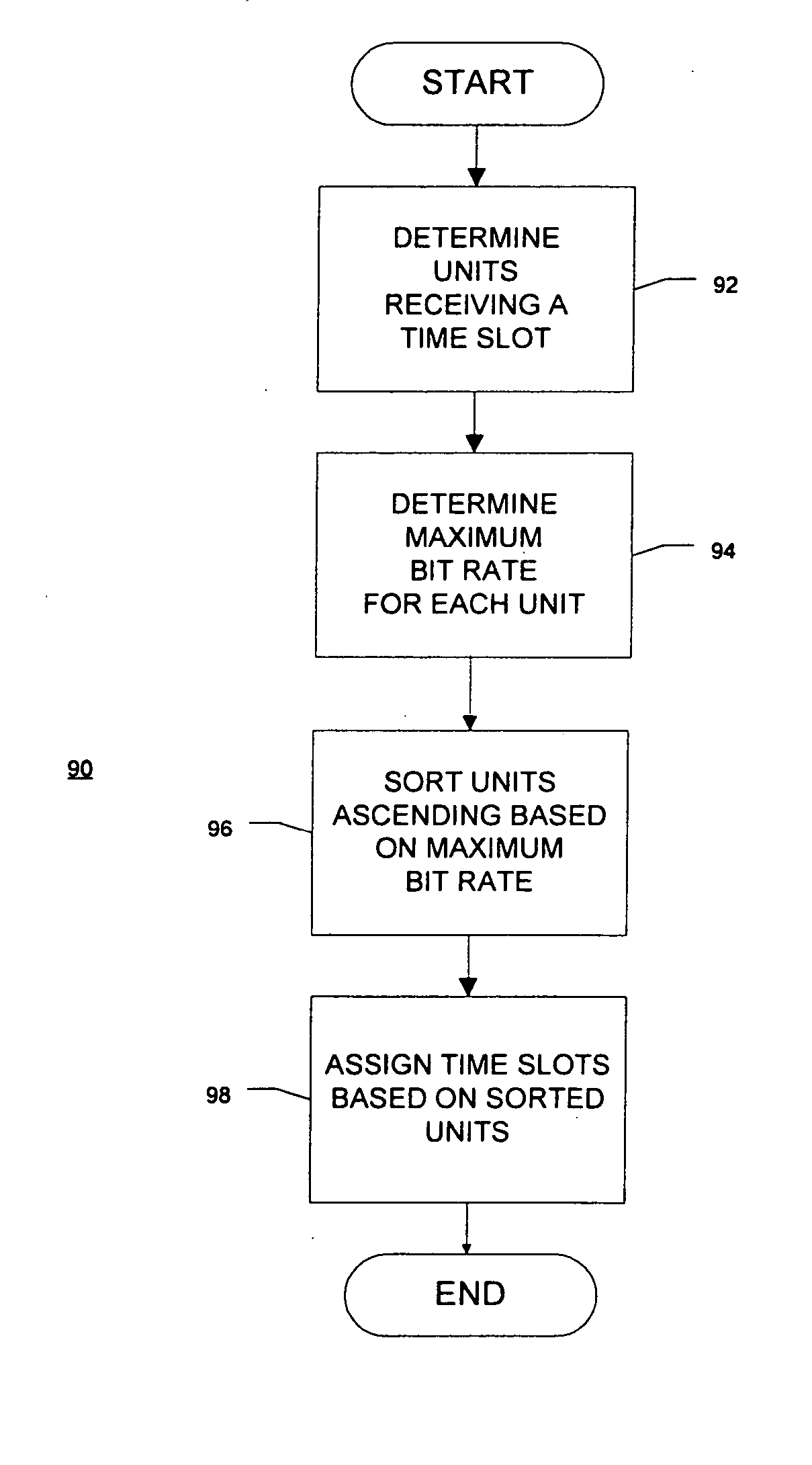
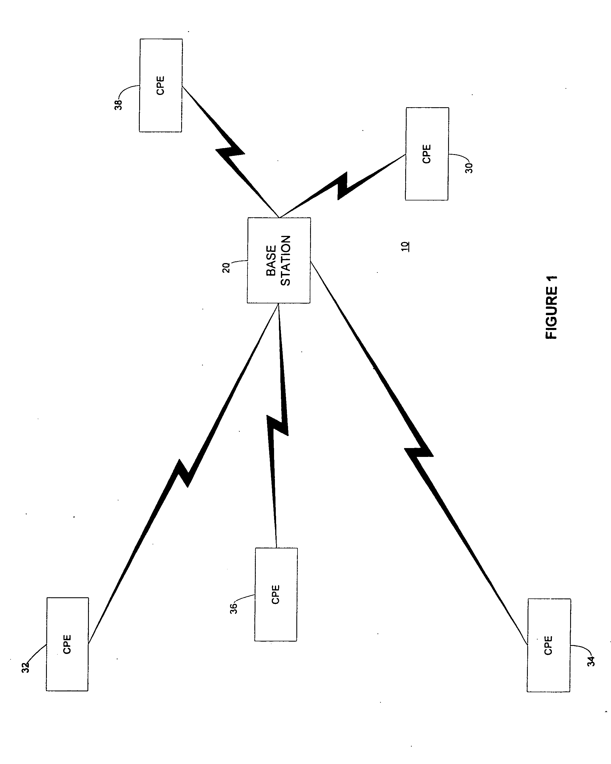
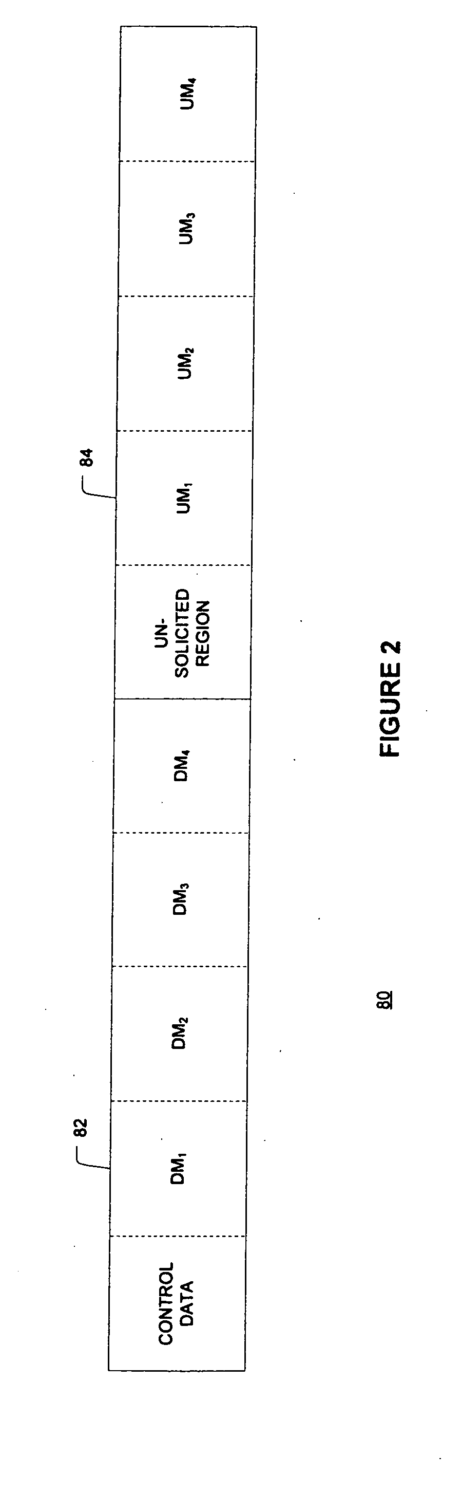
[0030] The present invention includes an improved frame structure and a process of generating a frame structure for use in wireless communication systems employing adaptive modulation. Adaptive modulation includes varying the bit per symbol rate modulation scheme or modulation complexity of signals transmitted between a CPE and a base station as a function of channel interference of the signals or implementation or modem complexity of the CPE. FIG. 1 is a diagram of an exemplary cell 10 that includes a base station 20 located centrally in the cell 10 and a plurality of CPEs 30, 32, 34, 36, 38 associated with the base station. FIG. 1 does not shown buildings or other physical obstructions (such as trees or hills, for example), that may cause channel interference between signals of the CPEs.

[0031] As described above, t...


PUM


Abstract

A method of assigning downlink time slots to receive units where the units may generate data using different modulation schemes. The method preferably assigns the downlink time slots as a function of the complexity of modulation schemes employed by the units. Further, the method preferably assigns the time slots from the least complex modulation scheme to the most complex scheme. The method may further assign uplink time slots to transmit units where the transmit units may generate data using different modulation schemes. The method preferably assigns the uplink time slots as a function of the complexity of modulation schemes employed by the uplink units. Further, the method preferably assigns the uplink time slots from the least complex modulation scheme to the most complex scheme. In other embodiments, the downlink time slots are assigned as a function of the bit per symbol rate employed by the receive units, preferably from the lowest bit per symbol rate to the highest bit per symbol rate. Further, the uplink time slots are assigned as a function of the bit per symbol rate employed by the transmit units, preferably from the lowest bit per symbol rate to the highest bit per symbol rate. The present invention is also a method of simplifying the encoding of a predetermined number of bits of data into frames. The method adds error coding bits so that a ratio of the frame length times the baud rate of the frame times the bit packing ratio of the data divided the total bits of data is always an integer. The method may also convolutionally encode the bits of data so that the same equation is also always an integer. The present invention is also a method of updating the weights of a FIR filter where the filter processes symbols having variable modulation rates. When the modulation rate of the incoming symbols changes, the weights corresponding to the first symbol having the new modulation rate are changed based as the symbol propagates through the filter.

Description

[0001] RELATED APPLICATIONS [0002] This application claims priority to and is a continuation of U.S. patent application Ser. No. 09 / 365,917. filed Aug. 3, 1999.BACKGROUND OF THE INVENTION [0003] 1. Field of the Invention [0004] This invention relates to frame structures for communication systems and more particularly to frame structures for adaptive modulation wireless communication systems. [0005] 2. Description of Related Art [0006] A wireless communication system facilitates two-way communication between a plurality of customer premises equipment (“CPE”) and a network infrastructure. Exemplary systems include mobile cellular telephone systems, personal communication systems (PCS), and cordless telephones. The objective of these wireless communication systems is to provide communication channels on demand between the users connected to a CPE and a base station in order to connect the user of a CPE with a network infrastructure (usually a wired-line system). In multiple access wire...

Claims


Application Information

Patent Timeline
Patent Type & Authority Applications(United States)
IPC IPC(8): H04B7/26H04J3/00H04L1/00H04L25/03H04L27/00
CPCH04B7/2656H04L1/0003H04L1/0004H04L1/0057H04L1/0059Y02B60/31H04L1/0083H04L25/03038H04L27/0008H04L2025/0342H04L2025/03477H04L1/0065Y02D30/50H04W72/0446H04W88/02H04W88/08
Inventor KLEIN, ISRAEL JAYSTANWOOD, KENNETH L.POLLMANN, STEVEPRICE, FREDERICK W.HADAR, RAMIARVIV, ELIGAZELLE, DAVIDGILBERT, SHELDON
Owner WI LAN INC
Why Eureka
Try Eureka