Relay apparatus, terminal apparatus and relay method

a relay method and terminal technology, applied in the field of relay methods, can solve the problems of increasing difficult to remove the interference of the echo wave, and wasting time, so as to reduce the size of the apparatus and reduce the waste of time

Active Publication Date: 2005-03-17
INTERDIGITAL PATENT HLDG INC
View PDF4 Cites 53 Cited by
  • Summary
  • Abstract
  • Description
  • Claims
  • Application Information

AI Technical Summary

Benefits of technology

[0012] It is an object of the present invention to provide a relay apparatus, terminal apparatus and relay method capable of realizing relay with reduced size of the apparatus and reduced waste of time without temporally switching between transmission and reception on a radio communication network on which bidirectional communication is performed.

Problems solved by technology

In this method, only one radio frequency band is used, however, since the received signal is transmitted after being stored, it is necessary to carry out transmission and reception at different times, which produces waste of time.
That is, the transmission antenna and reception antenna need to be disposed by keeping a sufficient distance from each other, which increases the size of the apparatus.
Furthermore, when a terminal apparatus requiring relay by the relay apparatus moves and it is impossible to suppress an amount of coupling between the transmission / reception antennas, it is difficult to remove interference of an echo wave and transmission quality degrades drastically.
Furthermore, a possibility that the relay apparatus may oscillate is also increased.
On the contrary, when relay is performed at the same frequency on a radio communication network on which bidirectional communication is carried out, a terminal apparatus transmitting a signal generally moves, the reception direction at the relay apparatus and the situation of the radio transmission path changes, resulting in a non-continuous communication with times during which one terminal apparatus is transmitting a signal and times during which the terminal apparatus is not transmitting any signal.
Therefore, simply introducing an echo canceller according to the aforementioned broadcasting technology results in a problem that it is not possible to realize relay with waste of time reduced using a small relay apparatus.

Method used


Image

  • Relay apparatus, terminal apparatus and relay method
  • Relay apparatus, terminal apparatus and relay method
  • Relay apparatus, terminal apparatus and relay method

Examples


embodiment 1

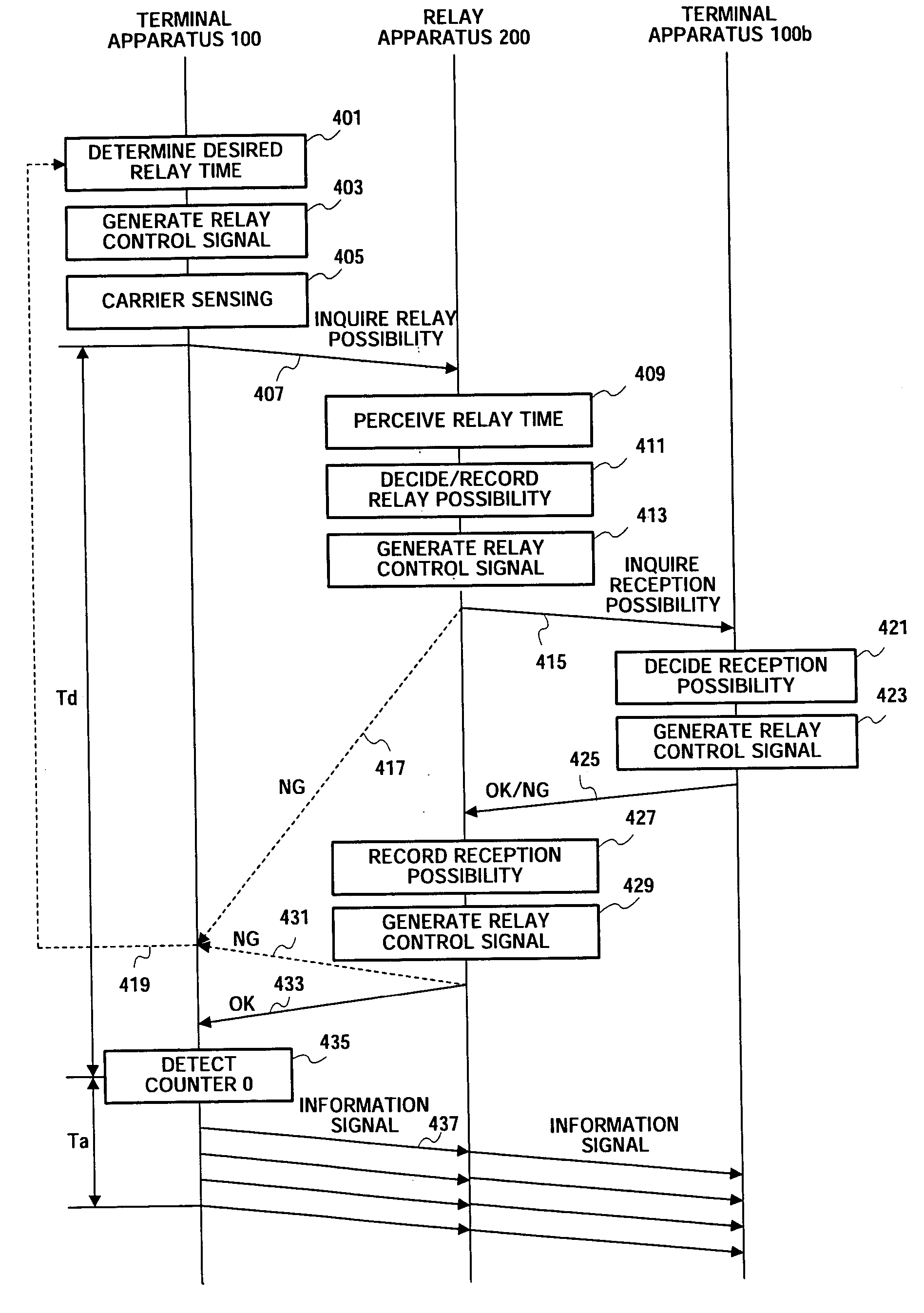
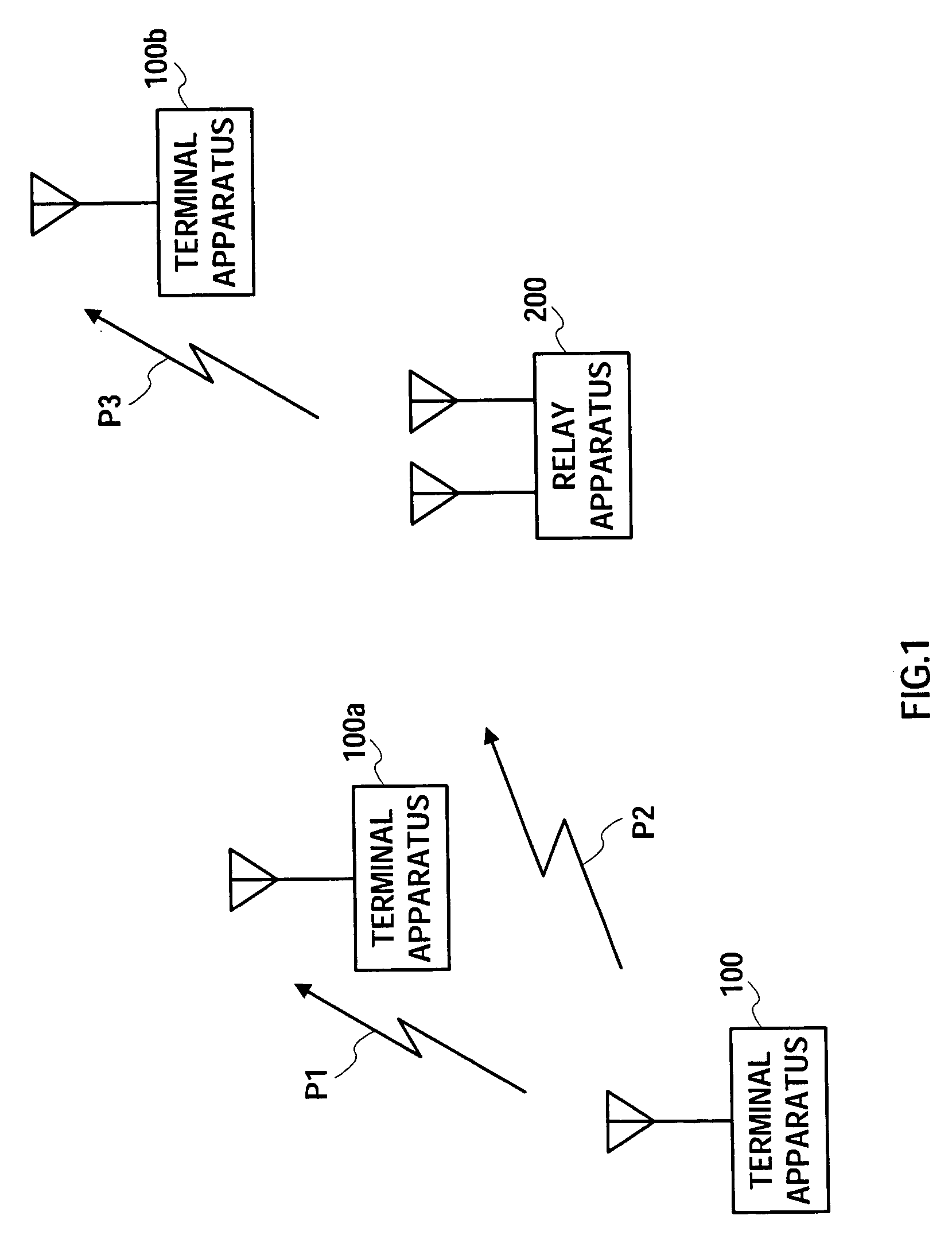
[0047]FIG. 1 illustrates an example of a configuration of a radio communication network according to Embodiment 1 of the present invention. As shown in the same figure, the radio communication network according to this embodiment is constructed of terminal apparatuses 100, 100a, 100b and relay apparatus 200.

[0048] The terminal apparatuses 100, 100a, 100b are all movable and the terminal apparatus 100 is relatively close to the terminal apparatus 100a, and therefore the terminal apparatus 100 transmits a signal to the terminal apparatus 100a, using a transmission path P1.

[0049] On the other hand, the terminal apparatus 100 is far from the terminal apparatus 100b and therefore the terminal apparatus 100 sends a signal to the relay apparatus 200 using a transmission path P2 and further the relay apparatus 200 sends the signal from the terminal apparatus 100 to the terminal apparatus 100b using a transmission path P3.

[0050]FIG. 1 shows communications between the terminal apparatuses ...

embodiment 2

[0126] A feature of Embodiment 2 of the present invention is to perform relay with a simple configuration without using any reservation table in deciding the possibility of relay and assumes the use of a procedure such as a DLP (Direct Link Protocol).

[0127] The relay apparatus according to this embodiment has the configuration of the relay apparatus 200 shown in FIG. 3 with the reservation table 2064 of the relay control signal processing section 206 removed.

[0128] This embodiment does not use any reservation table and prohibits transmission of a signal during a transmission prohibition period called “NAV (Network Allocation Vector)”. That is, each apparatus notifies other apparatuses of a scheduled period during which a radio channel and the other apparatuses do not send any signal during that period it is thereby possible to avoid collision of signals.

[0129] When two terminal apparatuses such as the terminal apparatus 100 and terminal apparatus 100b in FIG. 1 are in positions t...

embodiment 3

[0145] A feature of Embodiment 3 of the present invention is to superimpose a relay control signal and information signal on a plurality of subcarriers whose frequencies are orthogonal to one another to carry out transmission according to an OFDM (Orthogonal Frequency Division Multiplex) scheme.

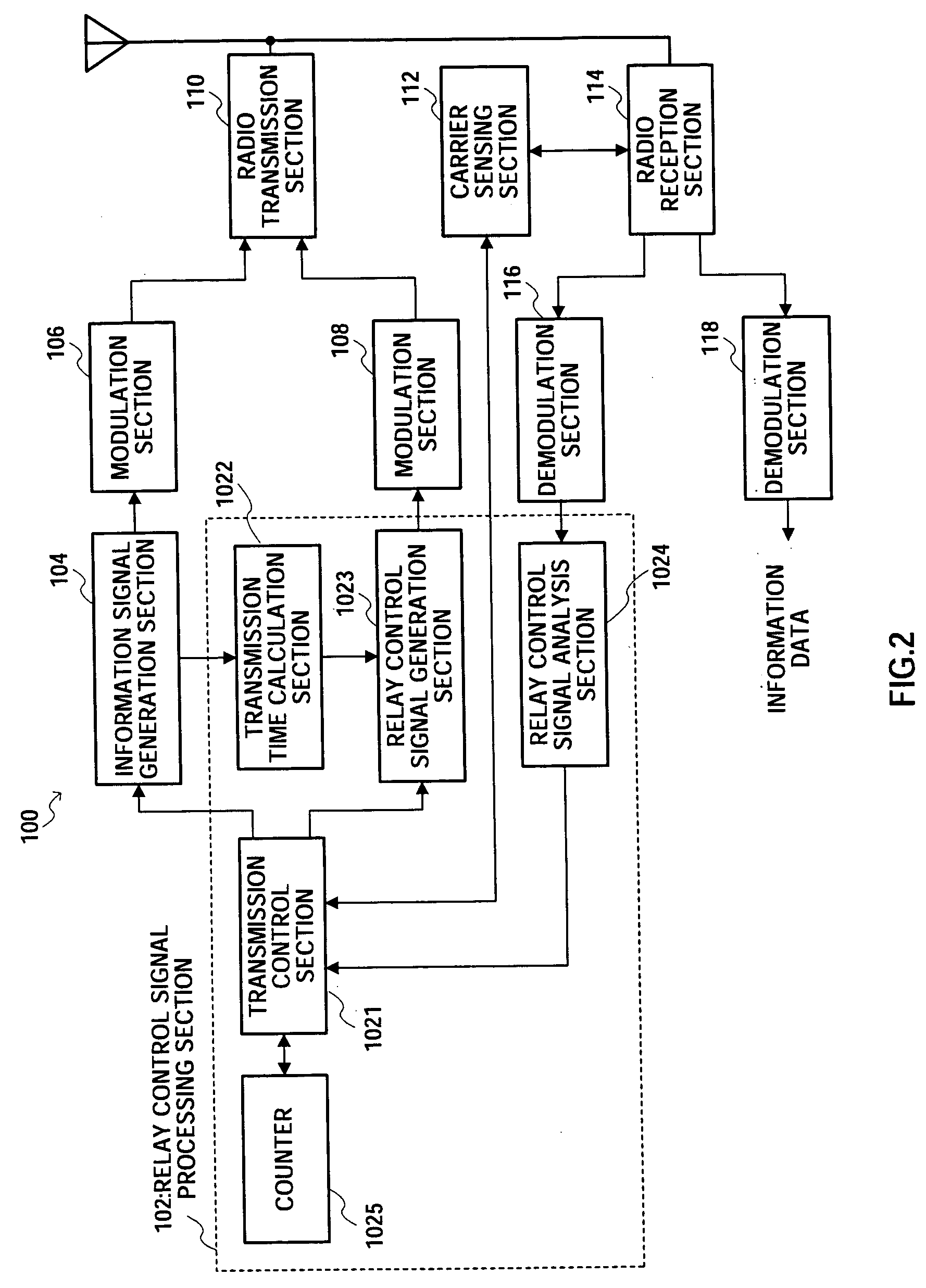
[0146]FIG. 10 is a block diagram showing a configuration of a terminal apparatus according to Embodiment 3 of the present invention. In the same figure, the same parts as those in FIG. 2 are assigned the same reference numerals and explanations thereof will be omitted. The terminal apparatus shown in FIG. 10 is provided with a relay control signal processing section 102, an information signal generation section 104, a modulation section 106, a modulation section 108, an S / P conversion section 302, an S / P conversion section 304, a multiplexing section 306, an IFFT (Inverse Fast Fourier Transform) section 308, a P / S conversion section 310, a GI (Guard Interval) addition section 312, a radio tr...


PUM


Abstract

A relay apparatus, terminal apparatus and relay method for relaying signals with a reduced scale of the apparatus, without temporally switching between transmission and reception and with reduced waste of time when relay is performed at the same frequency on a radio communication network on which bidirectional communication is performed. A radio reception section 202 outputs information signals to a switch 208, outputs relay control signals to a demodulation section 204 after subjecting predetermined radio reception processing. The demodulation section 204 demodulates a relay control signal. A relay control signal processing section 206 decides the possibility of relay of information signals and inquires, when the relay is possible, whether the terminal apparatus on the receiving side can receive this information signal or not. Furthermore, the relay control signal processing section 206 connects a switch 208 during the stored relay time. The switch 208 is connected only the information signals to be relayed are received under the control of a relay control section 2063.

Description

BACKGROUND OF THE INVENTION [0001] 1. Field of the Invention [0002] The present invention relates to a relay apparatus, terminal apparatus and relay method, and more particularly, to a relay apparatus, terminal apparatus, and relay method which relays signals at the same frequency on a radio communication network on which bidirectional communications between apparatuses are carried out. [0003] 2. Description of the Related Art [0004] Conventionally, this type of relay apparatus is disclosed in the Unexamined Japanese Patent Publication No.SHO 59-10043, for example. The Unexamined Japanese Patent Publication No.SHO 59-10043 discloses a method of relaying a signal with a same frequency for transmission and reception and improving a spectrum utilization efficiency by storing the received signal as a digital signal, reproducing and transmitting the stored signal. In this method, only one radio frequency band is used, however, since the received signal is transmitted after being stored, ...

Claims


Application Information

Patent Timeline
Patent Type & Authority Applications(United States)
IPC IPC(8): H04L5/14H04B1/707H04B7/015H04B7/15H04B7/155H04B7/26H04J11/00H04J13/00H04L27/26H04W16/26H04W84/18
CPCH04L27/2602H04B7/15528
Inventor YOMO, HIDEKUNIKUNIEDA, YOSHINORIYAMAMOTO, YUURIKAWAI, YOSHIHITO
Owner INTERDIGITAL PATENT HLDG INC
Why Eureka
Try Eureka