Image processing apparatus, image processing method and program

a technology of image processing and image processing method, applied in the field of image processing apparatus, method, program, can solve the problems of inability to correct this defect appropriately, the defective portion cannot be properly corrected, and the conventional interpolation-correction technique exemplified, etc., to achieve accurate correction of defective portion, reduce the amount of calculation needed, and increase processing speed

Inactive Publication Date: 2005-03-17
NORITZ CORP
View PDF10 Cites 39 Cited by
  • Summary
  • Abstract
  • Description
  • Claims
  • Application Information

AI Technical Summary

Benefits of technology

In view of the above-described state of the art, a primary object of the present invention is to provide an image processing technique capable of effecting accurate correction of a defective portion by detecting the direction where the defective portion is present and effecting an appropriate interpolation operation along that detected direction and which is capable also of increasing the processing speed with restricting the amount of calculation needed for the correction.
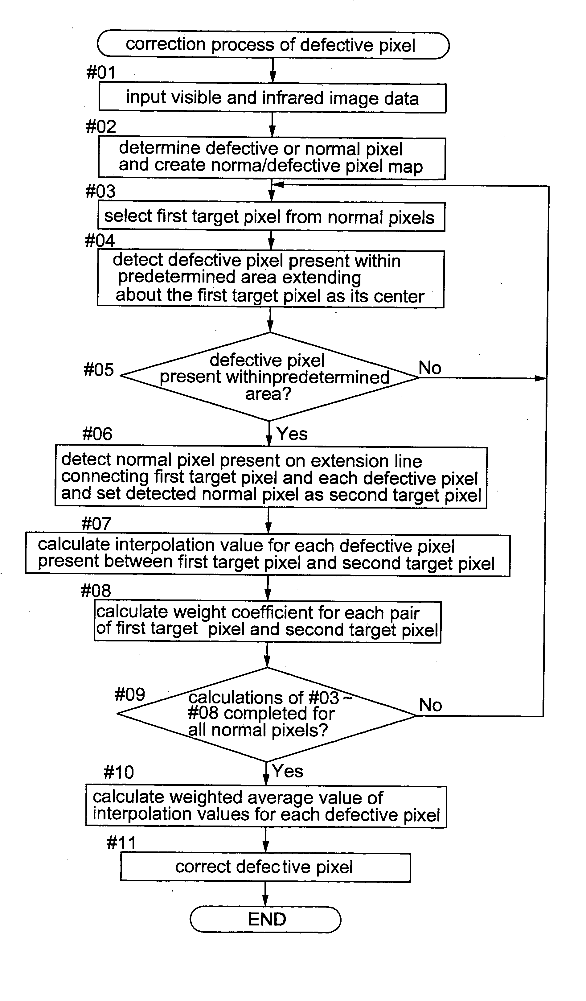
With the above-described construction, for each defective pixel, it is possible to obtain interpolation values based on pixel values of normal pixels present along a plurality of directions. Further, a weight coefficient for each direction is obtained in each direction, based on the pixel values of the normal pixels present in each direction around the defective pixel and a weighted average value of these weight coefficients is calculated and used for the final correction. Therefore, it is possible to obtain a final correction value reflecting an image boundary, pattern or the like present in each direction around the defective pixel. Consequently, it is possible to effect an appropriate interpolation operation with reflecting such image boundary, pattern or the like present in each direction around the defective pixel. Further, all of the interpolation values for one or two defective pixels present between the first target pixel and the second target pixel can be obtained by one time of calculation. As a result, it is possible to restrict the number of operations required for correction of all defective pixels included in image data. Hence, the amount of calculation may be reduced and the processing speed may be increased.
According to one preferred embodiment of the present invention, in said weight coefficient calculating section, either the pixel value of the first target pixel and the pixel value of the second target pixel whichever the greater is used as a denominator and whichever the smaller is used a numerator and a ratio thereof is raised to the nth power (n is a desired natural number) and this is calculated said weight coefficient. According to a further preferred embodiment of the present invention, in said weight coefficient calculating section, an absolute value of a difference between the pixel value of the first target pixel and the pixel value of the second target pixel is obtained, a complement of this absolute value relative to a predetermined value is obtained and this complement is then raised to the nth power (n is a desired natural number) and this result is calculated as said weight coefficient. According to these features, the weight coefficient can provide the greater weight for a pair of first target pixel and the second target pixel present across the defective value, whose respective values are the nearer each other. With such “enhancement” of the weight coefficient, it is possible to increase the effect of the interpolation value of the defective pixel calculated in the direction where the image boundary, edge or the like is present, to be exerted on the final correction value. As a result, the interpolation correction of the defective pixel can be carried out appropriately with reflecting presence of such image boundary, edge, pattern or the like. In this respect, the appropriate value of “n” will differ, depending on the condition of the image to be corrected. Therefore, preferably, this value should be experimentally obtained based on statistic data of various image data.
According to a still further preferred embodiment of the present invention, said interpolation value calculating section calculates the interpolation value for each defective pixel present between the first target pixel and the second target pixel by means of a linear interpolation of the pixel value of the first target pixel and the pixel value of the second target pixel. That is to say, the interpolation value for each defective pixel present between the first target pixel and the second target pixel can be calculated, based on the pixel values of the first and second target pixels present on the opposite sides thereof and distances relative respectively to the first target pixel and the second target pixel. In this way, appropriate interpolation values for all defective pixels can be calculated and obtained at one time. Therefore, it is possible to obtain appropriate interpolation values while restricting the number of calculates and increasing the processing speed.
With this method, the above-described function / effect of the image processing apparatus can be achieved. Hence, it is possible to effect an appropriate interpolation operation with reflecting such image boundary, pattern or the like present in each direction around the defective pixel. Further, the amount of calculation may be reduced and the processing speed may be increased.

Problems solved by technology

However, this luminance adjustment technique is based on an assumption that the pixel values of the respective color components of the defective portion have experienced an equal amount of luminance attenuation.
For this reason, if the amounts of attenuation in the pixel values of the respective color components differ from each other as may happen in the case of a scar in an emulsion surface on the film, the above technique cannot correct this defect appropriately.
However, if the defective portion includes a boundary (edge) or a pattern of the photographic image recorded on the film, such defective portion cannot be properly corrected by the above technique if it simply applies pixel values of adjacent non-defective pixels to the defective portion for its correction.
Yet, this conventional interpolation-correction technique exemplified by the Japanese Patent Application “Kokai” No. 2001-78038 discussed above still suffers a problem as follows.
Thus, this technique requires a great amount of calculation in total.
Hence, the technique requires a great amount of calculation for the calculations of the image attribute values and interpolation values, thus increasing the load on the calculating section such as a CPU.
Accordingly, it is difficult for this technique to increase its processing speed.

Method used


Image

  • Image processing apparatus, image processing method and program
  • Image processing apparatus, image processing method and program
  • Image processing apparatus, image processing method and program

Examples


Embodiment Construction

FIG. 1 is a perspective view showing an appearance of an image printing system 4. This image printing system 4 is adapted for reading an image from a photographic film 2 and then recording this read film image on a print paper 3 and includes an image processing apparatus relating to the present invention. FIG. 2 is a diagram showing a schematic construction of the image printing system 4. FIG. 3 is a block diagram showing the various functional units of the image processing apparatus 1.

As shown in these figures, this image printing system 4 includes an image reading device 5 for reading a photographically recorded image in each frame of the photographic film 2 developed by an unillustrated film developing device as digital image data, the image processing apparatus 1 configured for generating print data by effecting an image processing operation on the acquired image data, and an image recording device 6 configured for recording an image on the print paper 3 based on the print data...


PUM


Abstract

For correcting a defective portion in image data having a plurality of pixels, a plurality of first target pixels are selected one after another from normal pixels. Any defective pixel is detected within a predetermined area extending about each selected first target pixel as its center and also a normal pixel present on an extension line connecting the first target pixel and the defective pixel is detected and set as a second target pixel. For each defective pixel present between the first target pixel and the second target pixel, an interpolation value is calculated. Further, for each pair of the first target pixel and the second target pixel, a weight coefficient is calculated. The technique stores such plurality of interpolation values and weight coefficients. Then, by using the weight coefficient, a weighted average value of the interpolation values for each defective pixel is calculated and this weighted average value is used for the correction of each defective pixel.

Description

BACKGROUND OF THE INVENTION 1. Field of the Invention The present invention relates to an image processing apparatus, method, program and a medium storing the program for correcting a defective portion in image data having a plurality of pixels. In particular, the invention relates to an image processing technique for effecting an interpolating operation which allows appropriate correction or “retouching” of the image data even when a boundary (edge) or pattern portion of a photographically recorded image is present within its defective portion, by appropriately reflecting such boundary, pattern or the like in the correction. 2. Description of the Related Art A photographic film may include a defective portion on its surface, such as a scar, dust, dirt, etc. Then, when a photographically recorded image is read from such “defective” film to be printed on a print sheet or outputted on a display, there is known a technique available for correcting such defect by means of an image p...

Claims


Application Information

Patent Timeline
Patent Type & Authority Applications(United States)
IPC IPC(8): G06T5/00G06T1/00H04N1/40H04N1/409H04N5/232H04N5/253
CPCG06T5/005H04N1/4097
Inventor KITA, KOJI
Owner NORITZ CORP
Why Eureka
Try Eureka