
Device to detect individual moving objects having very small dimensions

a technology of moving objects and detectors, applied in the direction of optical radiation measurement, photometry using electric radiation detectors, instruments, etc., can solve the problems of large installation space, large measurement volume of photoelectric sensors without additional beam-forming optics that are available on the market, and large diameter of optical paths to detect very small individual objects with a high repeat rate and short object spacing,

Active Publication Date: 2005-03-17
MINEBEAMITSUMI INC
View PDF5 Cites 7 Cited by
  • Summary
  • Abstract
  • Description
  • Claims
  • Application Information

AI Technical Summary

Benefits of technology

[0004] The object of the invention is to provide a device to detect individual moving objects having very small dimensions which is capable of detecting and analyzing a change in the light signals caused by the passing objects in such a way that each individual through moving object can be reliably recognized.
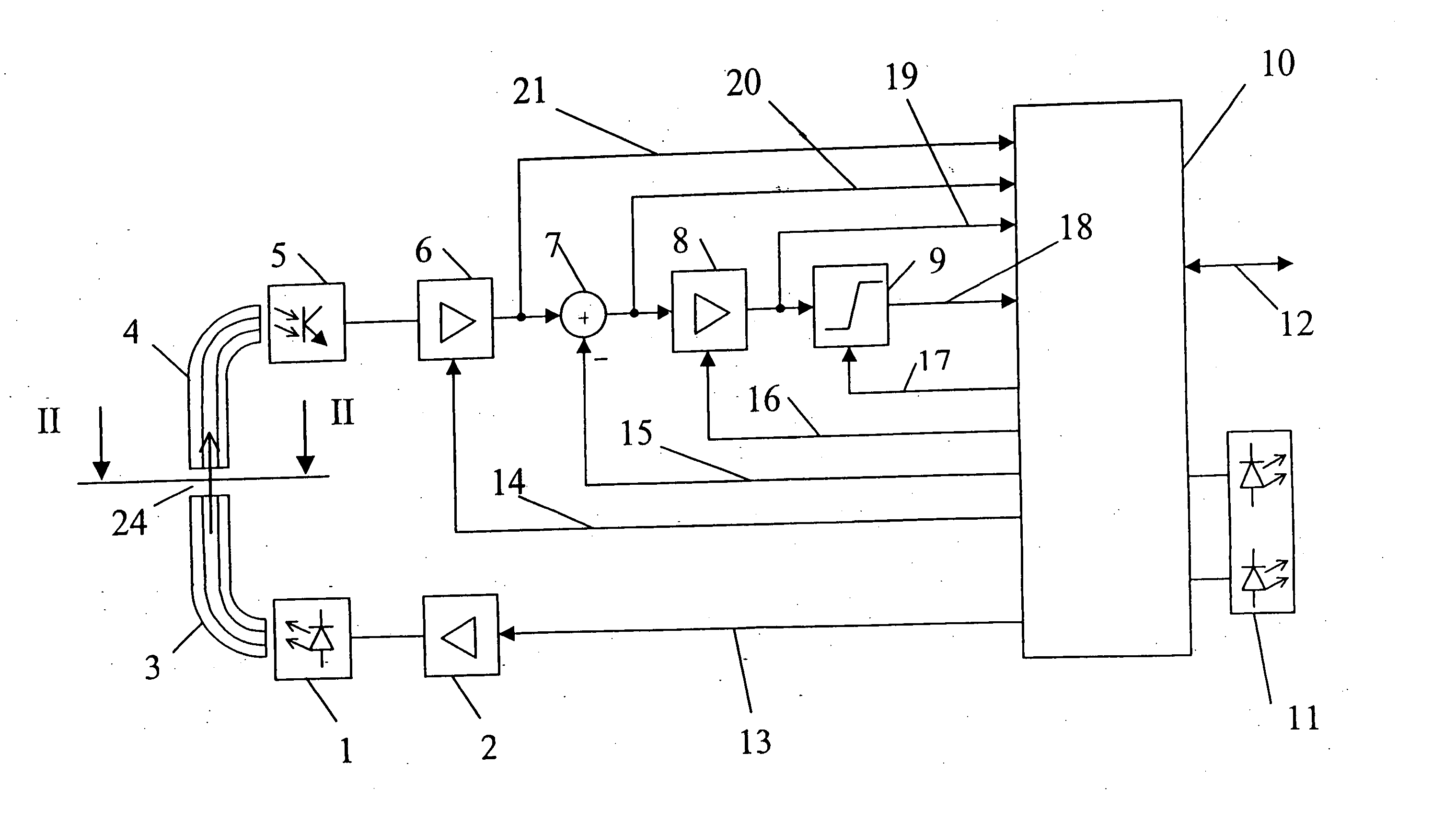
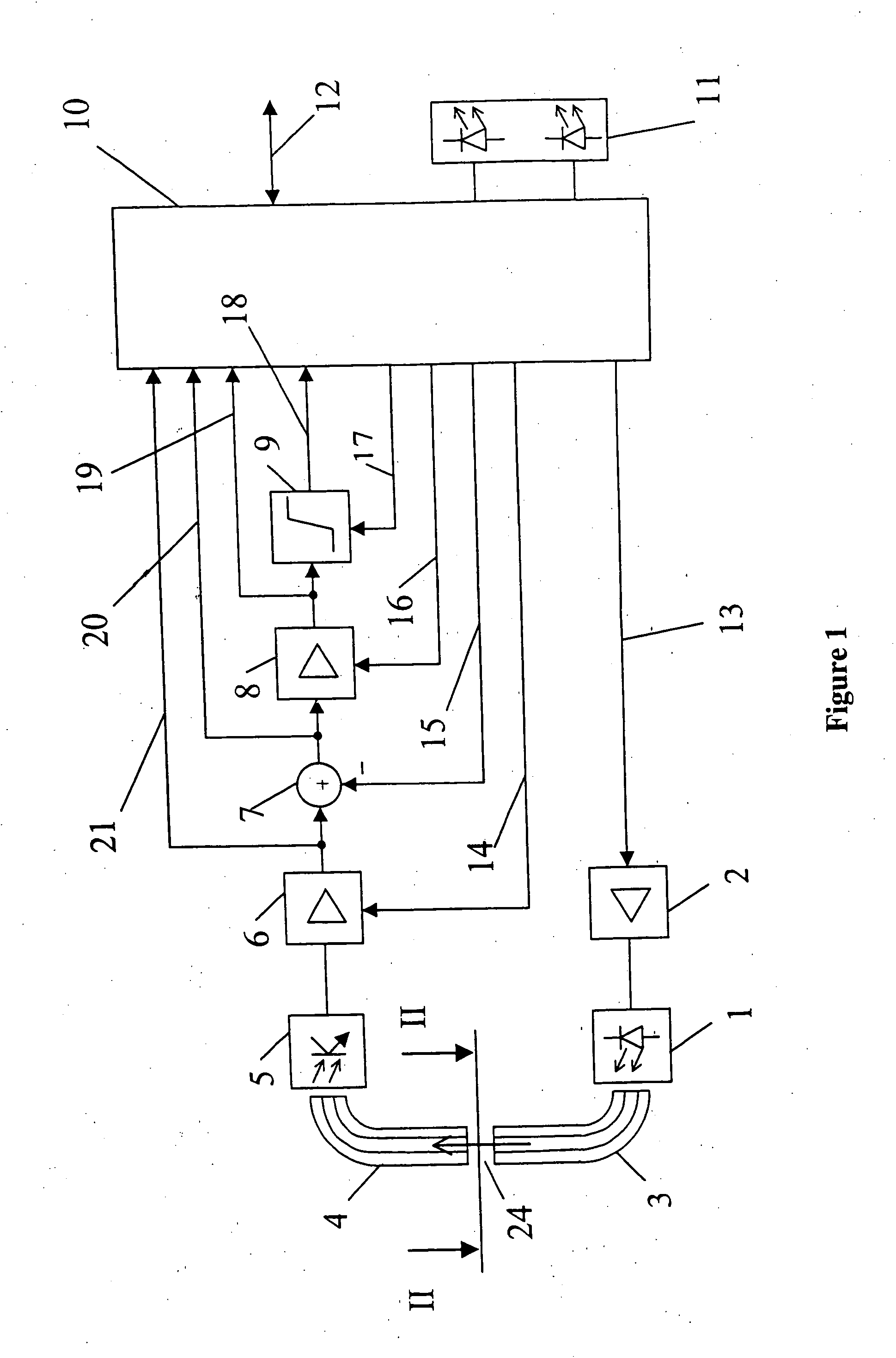
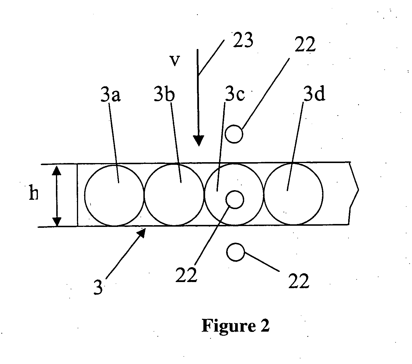
[0007] In accordance with the invention, to detect the small objects both the very small mechanical dimensions as well as the optical coupling characteristics of the optical waveguides are exploited. The mechanical dimensions of the optical waveguides are in the order of magnitude of the objects that are to be measured which means that additional beam-forming optical elements to recognize the objects are not required. Moreover, the coupling characteristics of the waveguides when installed, particularly the restricted incoming beam angle typical of optical waveguides, prevent the input of optical interfering signals produced by outside sources of light. To make the optics tolerant to mechanical installation tolerances, several wave guides are arranged in one line. The width of the line in conjunction with its height gives the detection volume.
[0010] In a preferred embodiment of the invention, the optical waveguides of the first bundle and the second bundle are arranged parallel to each other, the outputs of the first bundle of optical waveguides are arranged in a plane with the inputs of the second bundle of optical waveguides and are located opposite them. The optical path of the photo electric sensor takes the approximate shape of a disk whose thickness is within the order of magnitude of the objects that are to be measured, the cross-section of the detection volume in the direction of movement of the objects being significantly smaller than the cross-section transversal to the direction of movement of the objects. The narrow, disk-shaped detection volume produces very good detection sensitivity for small objects following each other at a rapid rate.
[0013] The microprocessor control enables the evaluation electronics to be optimally adapted to the operating range of the individual components with the aid of variable amplification factors of the amplifier, a subtraction of offsets, an adjustable switching threshold of the threshold value switch and a variable light intensity of the light beam transmitter. The electronics can be automatically compensated for environmental influences, component aging, soiling of the photo electric sensor etc.

Problems solved by technology

The measurement volumes of photo electric sensors without additional beam-forming optics that are available on the market are too large, that is, the diameter of the optical path is too large to detect very small individual objects with a high repeat rate and with short object spacing.
Beam-forming optics that could remedy this problem need a large installation space compared to the very small objects.
If there is only a restricted installation space available, these kinds of photo electric sensors cannot be employed.
Particularly in the case of very small objects, however, environmental influences, electrical disturbances and transit phenomena result in faulty detection since the signal picked up by the light beam receiver is very small compared to the interfering signals.
These kinds of evaluation circuits do not produce a counting result that is sufficiently reliable in order to count, for example, drops of liquid that have a diameter of 200 μm or less.

Method used


Image

  • Device to detect individual moving objects having very small dimensions
  • Device to detect individual moving objects having very small dimensions
  • Device to detect individual moving objects having very small dimensions

Examples


Embodiment Construction

[0017] A possible application of the invention could be seen in counting drops of liquid, particularly drops with a diameter in the sub-mm range. Such small drops can be produced by a microdispenser. The microdispenser shoots out drops having a diameter of less than 100 μm from a jet. For many applications, it is necessary to count every single drop that leaves the microdispenser. With a drop speed of approx. 2 m / s and a repeat frequency of 2000 Hz to 4000 Hz, counting the individual drops is made difficult. However, the device according to the invention solves this problem without difficulty.

[0018] As can be seen from FIG. 1, the device comprises a light beam transmitter 1, such as a light-emitting diode or a laser diode that is controlled by a driver 2. The light is fed to a first bundle of optical waveguides 3 whose inputs are connected to the light beam transmitter 1. The input cross-section of the bundle of optical waveguides is adjusted to the cross-section of the light beam ...


PUM


Abstract

The invention relates to a device to detect individual moving objects having very small dimensions. The device according to the invention comprises a photo electric sensor having at least one light beam transmitter and one light beam receiver, the objects that are to be measured moving through the optical path of the photo electric sensor, a first bundle of optical waveguides whose inputs are connected to the light beam transmitter and whose outputs are arranged in a row alongside each other, the light beams emitted by the outputs forming the optical path of the photo electric sensor, a second bundle of optical waveguides which are arranged in a row alongside each other whose inputs pick up the light beams emitted by the first bundle of optical waveguides and whose outputs are connected to the light beam receiver, and an evaluation unit which is coupled to the light beam transmitter and the light beam receiver and which registers a change in the received light intensity of the photo electric sensor produced by the objects passing through the optical path.

Description

BACKGROUND OF THE INVENTION [0001] The invention relates to a device to detect individual moving objects having very small dimensions, particular dimensions in the sub-mm range. [0002] Photo electric sensors are frequently used to detect moving objects. The measurement volumes of photo electric sensors without additional beam-forming optics that are available on the market are too large, that is, the diameter of the optical path is too large to detect very small individual objects with a high repeat rate and with short object spacing. Beam-forming optics that could remedy this problem need a large installation space compared to the very small objects. If there is only a restricted installation space available, these kinds of photo electric sensors cannot be employed. [0003] Existing evaluation electronics analyze the changes in the signal when an object passes through and thus recognizes the objects. Particularly in the case of very small objects, however, environmental influences, ...

Claims


Application Information

Patent Timeline
IPC IPC(8): G01J1/02G01V8/20G01J1/42G01N15/14G01V8/16G06T1/00
CPCG01V8/16G01N2015/1486
Inventor ARNOLD, MARTINIRMER, NORBERTSCHILL, HUBERTHEINZLER, MARKUS
Owner MINEBEAMITSUMI INC
Learn More