
Estimation of a signal delay

a signal delay and estimation technology, applied in the field of signal delay estimation, can solve the problems of increasing the length of the searching range generally affecting the false alarm rate of the acquisition of signals, so as to reduce the false alarm rate, increase the acquisition probability, and reduce the amount of noise components

Active Publication Date: 2005-03-17
META PLATFORMS INC
View PDF9 Cites 8 Cited by
  • Summary
  • Abstract
  • Description
  • Claims
  • Application Information

AI Technical Summary

Benefits of technology

[0018] It is an advantage of the invention that it reduces the false alarm rate and increases the acquisition probability when determining the location of a mobile station, e.g. in a location service. In addition, the amount of noise components is reduced, e.g. to one half.

Problems solved by technology

On the one hand, this threshold has to be set high enough in order to avoid that a noise peak is detected as the signal edge, which would result in a false alarm.
It is known from the searching procedures for delayed signals, however, that the length of the searching range generally affects the false-alarm rate in the acquisition of a signal.
The longer the searching range, the higher the false alarm rate will be.
The problem is even more severe for location services, since the signals are partly much weaker and the noise is higher for neighboring network elements, while the delays are bigger.
The majority of the noise is the interference caused by the server network element when acquiring the neighboring network element.
The same kind of problems may occur in other cellular network based positioning procedures.

Method used


Image

  • Estimation of a signal delay
  • Estimation of a signal delay
  • Estimation of a signal delay

Examples


Embodiment Construction

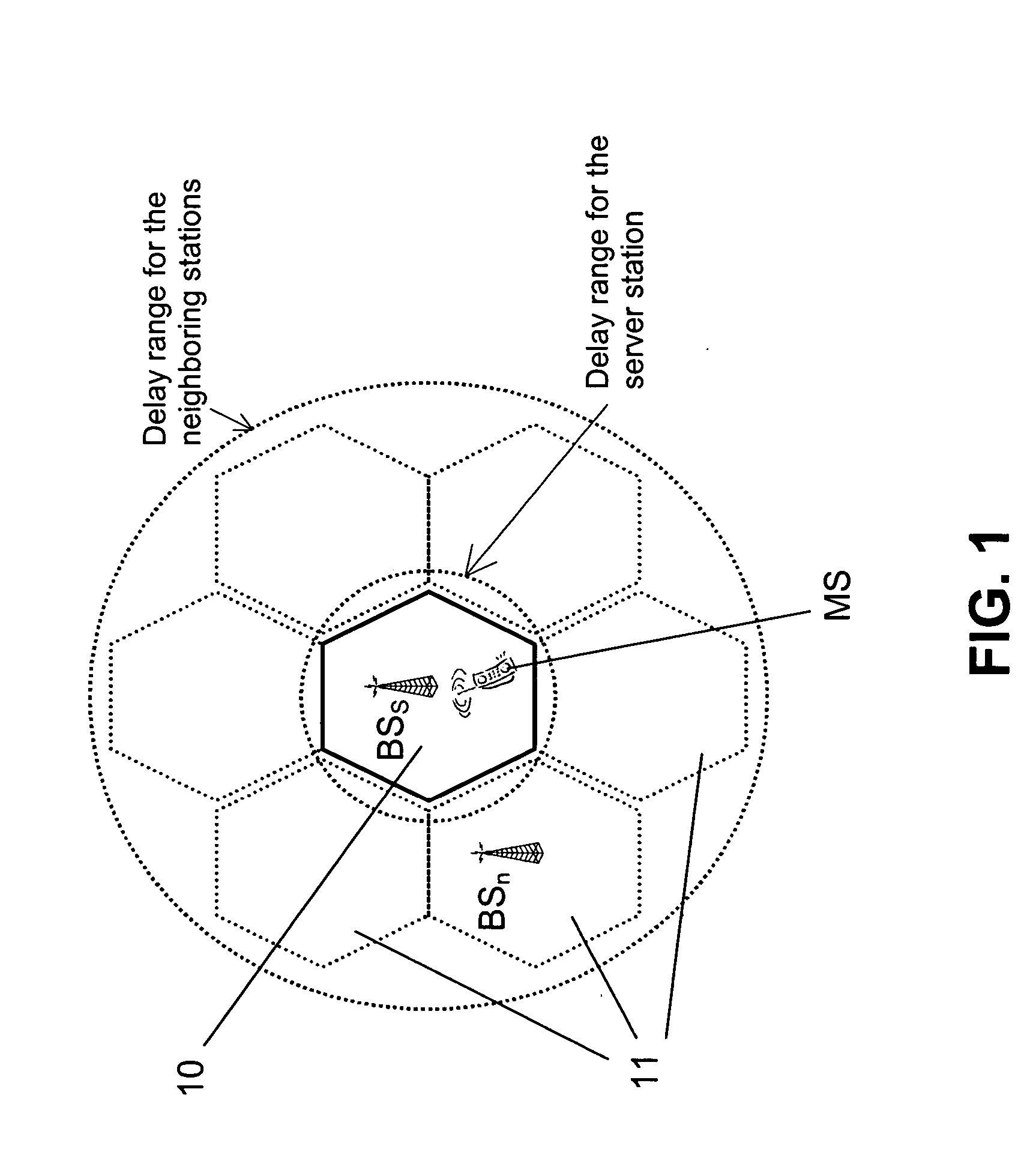
[0038]FIG. 1 has already been described above.

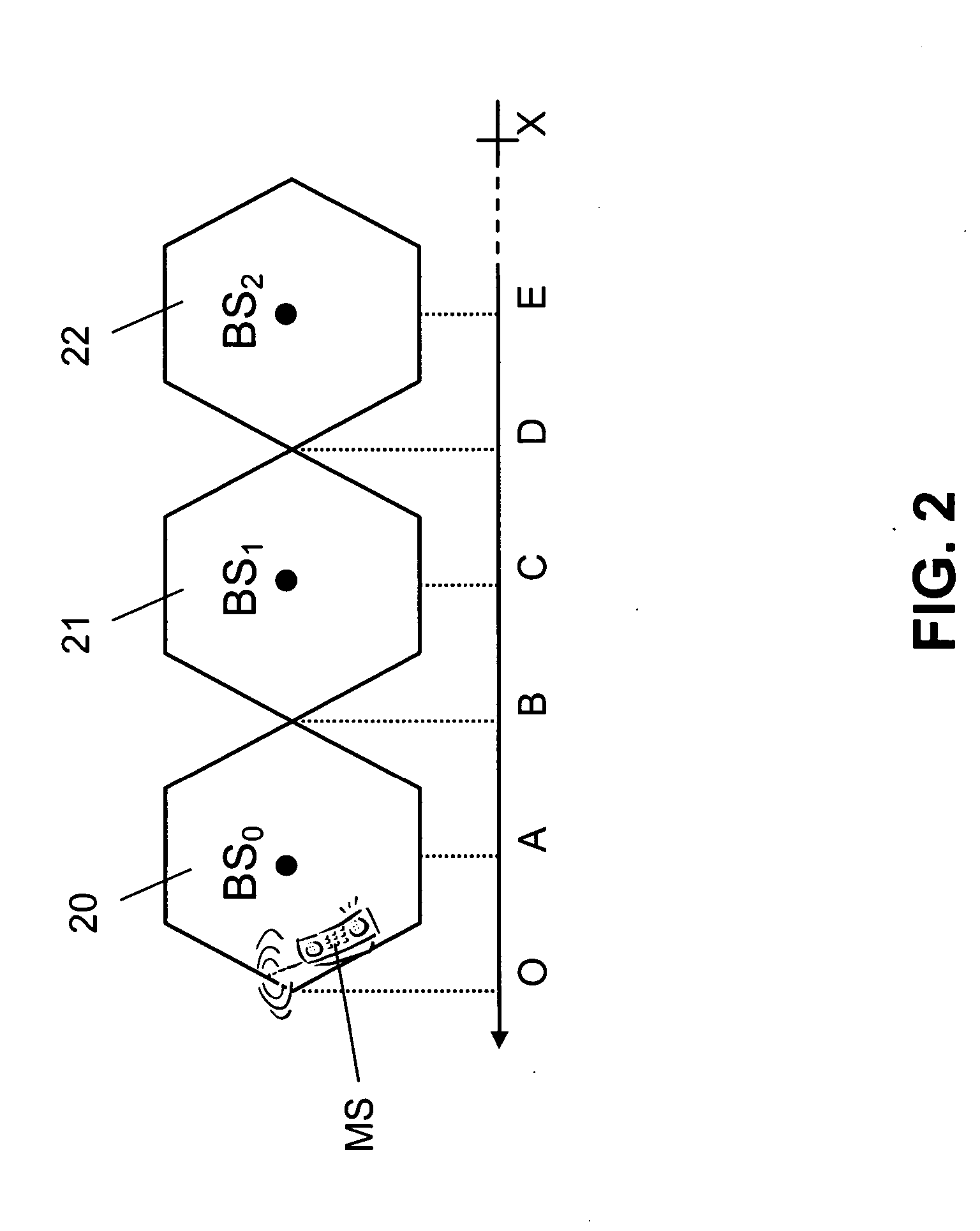
[0039]FIGS. 2 and 3a-3c illustrate by way of example the principle of the method according to the invention employed in a cellular communication system. The communication system comprises a mobile station and a cellular network with a plurality of cells, each of which is served by another base station. The communication system enables certain location services. Currently, the location of the mobile station is to be determined using these location services.

[0040]FIG. 2 indicates various distances in the communication system. Several cells 20, 21, 22 of the cellular network are arranged in a row. A straight line depicted in parallel to this row associates different letters O, A to E, . . . , X to different locations in the communication system. Locations A to D are equidistant from the respective neighboring locations.

[0041] The mobile station MS is located in a server cell 20. The server cell 20 extends from location O to location B. A...


PUM


Abstract

The invention relates to a method for estimating a delay of a signal received at a mobile station MS from a specific network element BS1, BS2 of a network for determining the location of the mobile station. In order to reduce the false alarm ratio and to increase the acquisition probability, it is proposed that the method comprises estimating the delay within a search window. The search window is determined based on location information available for the specific network element BS1, BS2 and on a known distance of the mobile station MS to at least one other network element BS0, BS1. The invention relates equally to a corresponding mobile station MS, to a corresponding network element BS0, and to a communication system comprising at least one mobile station and at least two network elements.

Description

CROSS REFERENCE TO RELATED APPLICATIONS [0001] This application claims priority under 35 USC §119 to International Patent Application No. PCT / IB02 / 05055 filed on Dec. 2, 2002.FIELD OF THE INVENTION [0002] The invention relates to a method for estimating a delay of signals received at a mobile station from a specific network element of a network for determining the location of the mobile station. The invention relates equally to a mobile station, to a network element of a network and to a communication system. BACKGROUND OF THE INVENTION [0003] The location of a mobile station can be determined by a positioning procedure, for example a positioning procedure which is part of a location service. [0004] Location services in cellular systems are based on determining the delay of signals transmitted by different network elements of a cellular network to a mobile station of which the location is to be determined. In case of a line-of-sight transmission, the delay of the signals is directly...

Claims


Application Information

Patent Timeline
IPC IPC(8): H04W64/00
CPCH04W64/00
Inventor ZHENGDI, QIN
Owner META PLATFORMS INC
Learn More