This helps you quickly interpret patents by identifying the three key elements:
Problems solved by technology
Method used
Benefits of technology
[0011] In the diversity receiver in accordance with the present invention, the estimation unit preferably zero clears the time series data of the m
Problems solved by technology
As a result, a code error frequently occurs in digital transmission.
However, with the above-described prior art technology, i
Method used
Image
Click on the blue label to locate the original text in one second.
Reading with bidirectional positioning of images and text.
Examples
Example
[0015] Embodiment 1
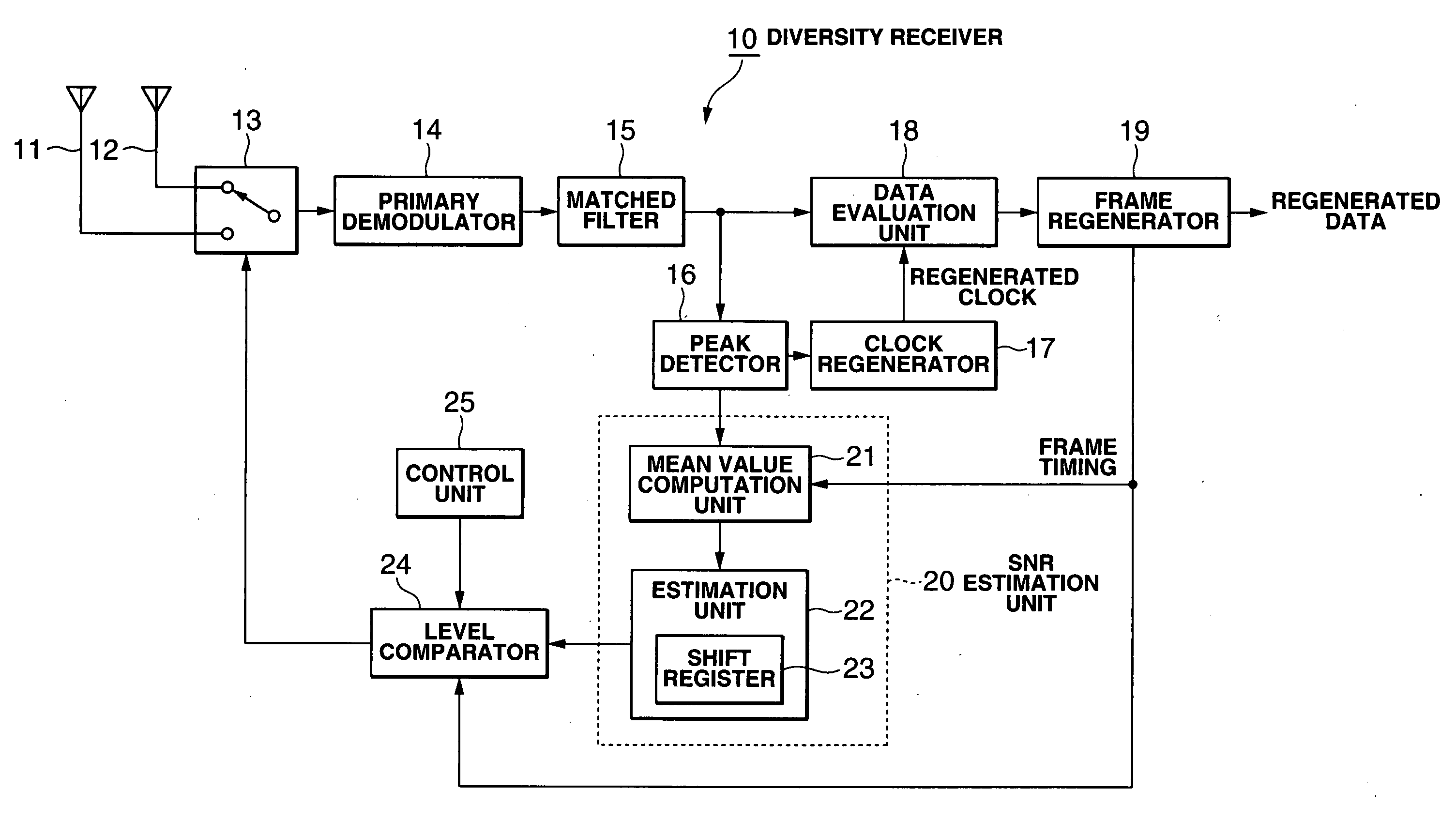
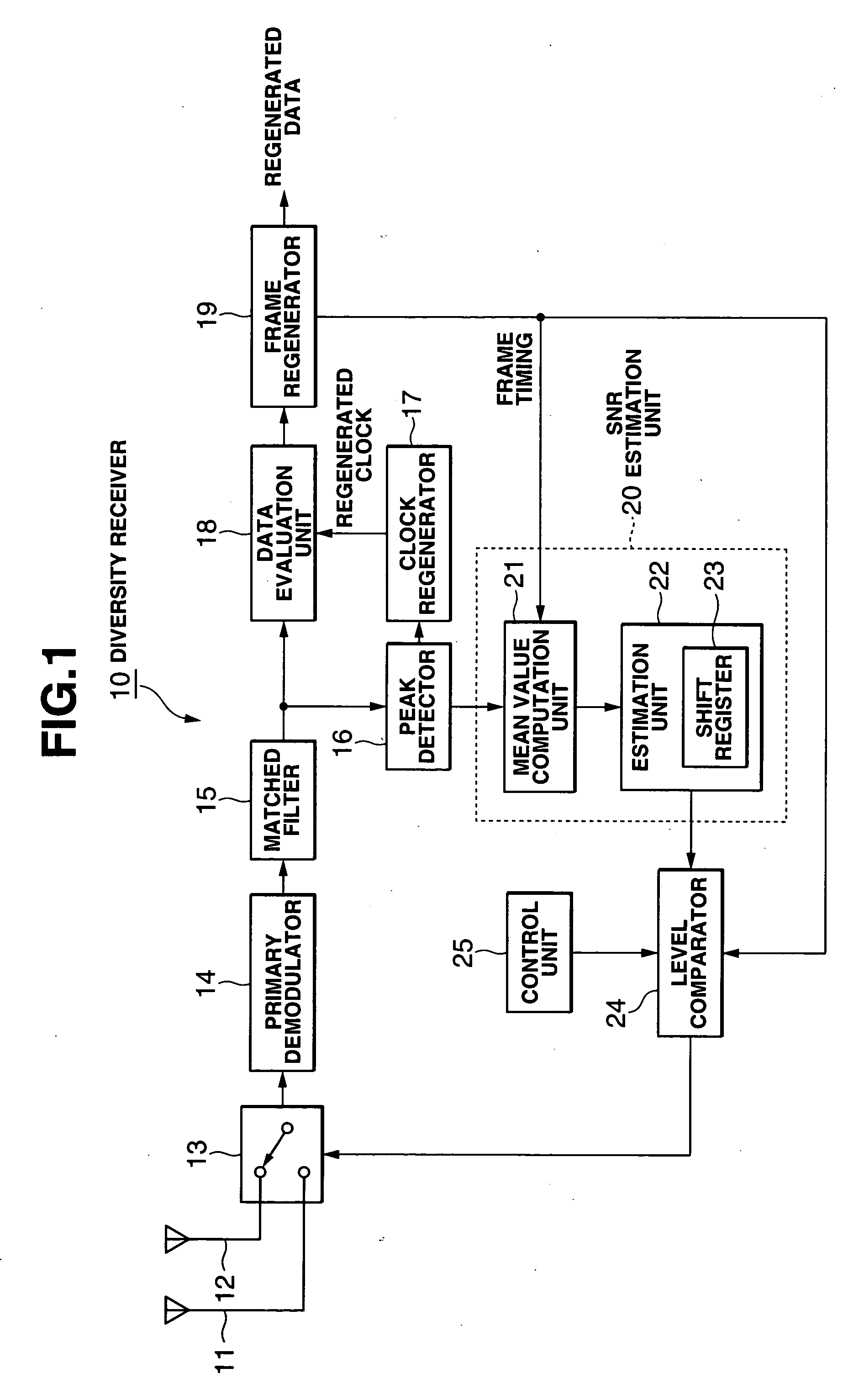
[0016]FIG. 1 is a functional block diagram of the diversity receiver used in the direct spread spectrum communication system. As shown in the figure, a diversity receiver 10 is composed mainly of a plurality of antennas 11, 12, an antenna switch 13, a primary demodulator 14, a matched filter 15, a peak detector 16, a clock regenerator 17, a data evaluation unit 18, a frame separator 19, a SNR estimation unit 20, a level comparator 24, and a control unit 25.
[0017] In direct spread spectrum communication, a spread spectrum signal of a base band is generated by multiplying the data which is to be transmitted by a spread code. At the transmitting side of the spread spectrum communication system, a wireless signal obtained by modulating the propagating wave (carrier) with this base-band spread spectrum signal (chip data) is transmitted. This wireless signal arrives at antennas 11, 12. The primary demodulator 14 demodulates the wireless signal received via the antenna...
Example
[0028] Embodiment 2
[0029]FIG. 3 is a functional block diagram of a diversity receiver in a M-ary / DS system. As shown in the figure, a diversity receiver 30 mainly comprises a plurality of antennas 11, 12, an antenna switch 13, a primary demodulator 14, a total of N matched filters 15-1, 15-2, . . . , 15-N, a peak detector 16, a clock regenerator 17, a data evaluation unit 18, a frame separator 19, a SNR estimation unit 20, a level comparator 24, a control unit 25, and a maximum value detection unit 26.
[0030] The primary demodulator 14 demodulates the wireless signal received via the antenna 11 or 12 selected by the antenna switch 13 and outputs the chip data as a detection output. A total of N matched filters 15-1, 15-2, . . . , 15-N arranged in parallel, the number thereof corresponding to the M-ary system series number N, are connected to the last stage of the primary demodulator 14, and chip data is supplied to each matched filter 15-1, 15-2, . . . , 15-N. The maximum value det...
PUM
Abstract
It is an object of the present invention to improve the diversity gain by conducting linear prediction of fading fluctuations and switching antennas. In order to attain this object, the diversity receiver in accordance with the present invention comprises a plurality of antennas for receiving wireless signals subjected to direct spread modulation, an antenna switch for conducting antenna connection switching thereof, a primary demodulator for demodulating the wireless signals and obtaining a spread spectrum signal, a matched filter for finding a correlation value of the spread spectrum signal and a spread code for demodulation, a mean value computation unit for finding a mean SNR of the received signal by converting the maximum correlation value to a value per 1 frame, an estimation unit for linear prediction of the SNR of the received signal based on the time series data of the mean SNR, and a level comparator for comparing the SNR of the received signal that was predicted by the estimation unit with a threshold value and outputting a control signal for conducting antenna switching to the antenna switch.
Description
BACKGROUND OF THE INVENTION [0001] 1. Field of the Invention [0002] The present invention relates to a diversity reception technology for wireless systems using a direct spread spectrum communication method. [0003] 2. Description of the Related Art [0004] In mobile communications, fading occurs in a multipass environment. If fading occurs, the received input is subjected to significant level fluctuations and phase fluctuations of several tens of dB. As a result, a code error frequently occurs in digital transmission. Diversity reception methods were suggested as a fading countermeasure. Among such methods, antenna switching diversity is suitable for wireless systems requiring simplification of system structure, such as mobile stations. Japanese Patent Application Laid-open No. 2003-46418 disclosed a technology by which in a wireless system using spread spectrum communication, antenna switching is conducted by comparing a threshold value and an average maximum correlation value which...
Claims
Application Information
Patent Timeline
Application Date:The date an application was filed.
Publication Date:The date a patent or application was officially published.
First Publication Date:The earliest publication date of a patent with the same application number.
Issue Date:Publication date of the patent grant document.
PCT Entry Date:The Entry date of PCT National Phase.
Estimated Expiry Date:The statutory expiry date of a patent right according to the Patent Law, and it is the longest term of protection that the patent right can achieve without the termination of the patent right due to other reasons(Term extension factor has been taken into account ).
Invalid Date:Actual expiry date is based on effective date or publication date of legal transaction data of invalid patent.