Obstacle detection system for underground operations

a detection system and underground operation technology, applied in the field of electromagnetic sensing devices, can solve the problems of significant repair and loss of service, the potential hazard of cutting existing underground utilities, and the magnitude of problems, so as to maximize the detection maximize the forward and maximize the side-looking capability or sensitivity of the sensor

Active Publication Date: 2005-03-24
GAS TECH INST
View PDF10 Cites 21 Cited by
  • Summary
  • Abstract
  • Description
  • Claims
  • Application Information

AI Technical Summary

Benefits of technology

According to one embodiment of the present invention, a single obstacle detection sensor may be used to detect objects proximate the cutting tool. The single sensor is positioned at a suitable location on the cutting tool so as to maximize the detection capability or sensitivity of the sensor. For example, the single sensor may be located proximate the leading edge of the cutting tool in a forward-looking orientation, on the cutting tool in a side looking orientation, or at a location that provides a balance between forward- and side looking orientations. Alternatively, the sensor may be located on the cutting tool body, but be so designed that it is sensitive to or receives signals back from objects ahead of or slightly to the side of the tool body.
According to another embodiment, multiple object detection sensors may be deployed at various locations within

Problems solved by technology

However, with this installation ease and lower cost, there is the potential hazard of cutting existing underground utilities and the significant cost incurred for repair and loss of service.
Even though not all these utility hits were the result of directional drilling operations, the magnitude of the problem is evident.
Companies responsible for cuts are also be

Method used


Image

  • Obstacle detection system for underground operations
  • Obstacle detection system for underground operations
  • Obstacle detection system for underground operations

Examples


Embodiment Construction

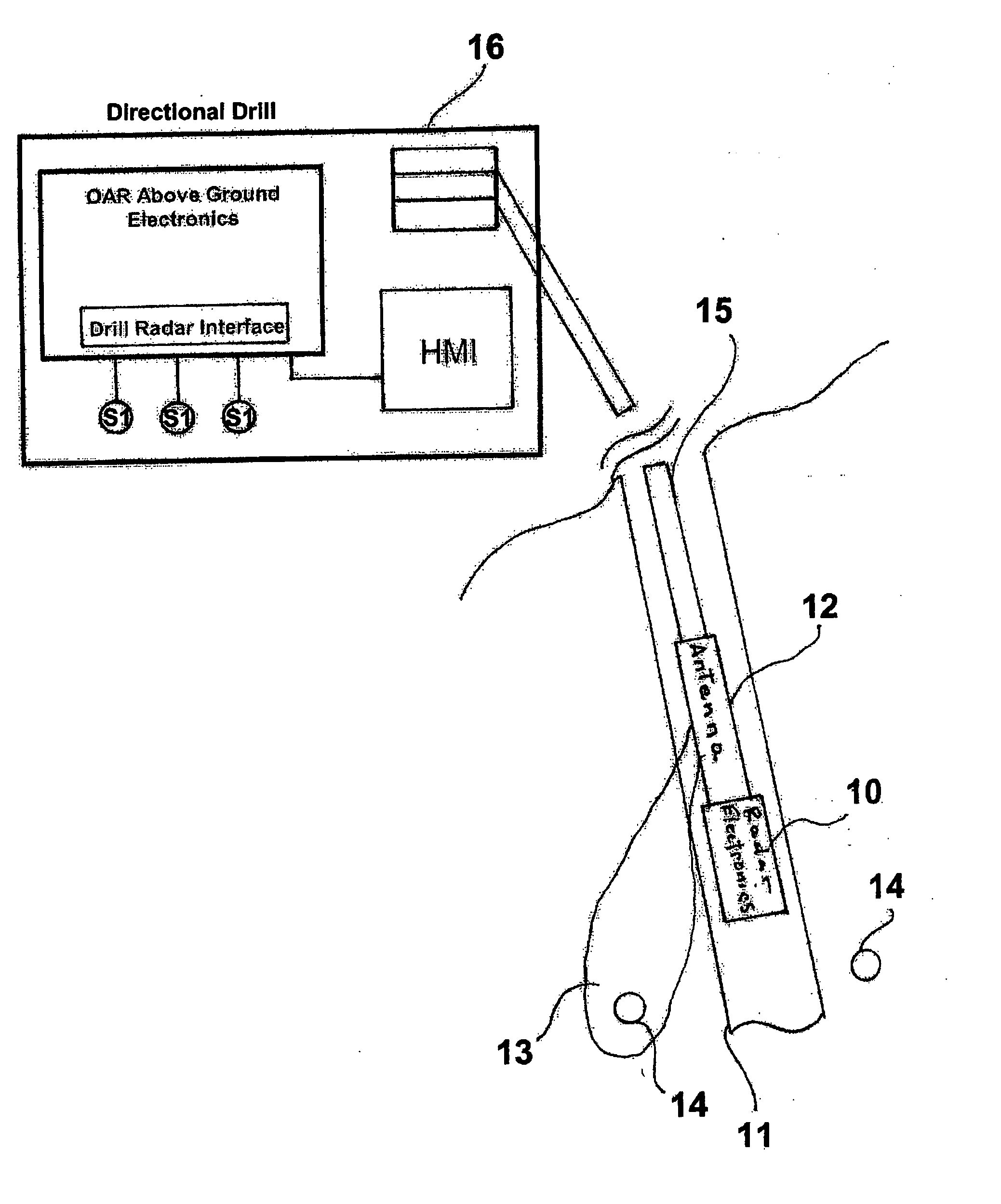
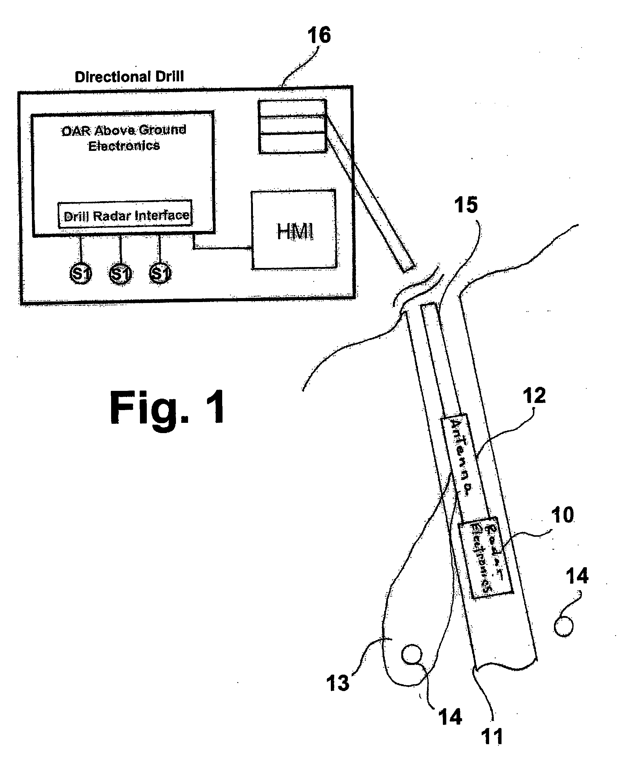
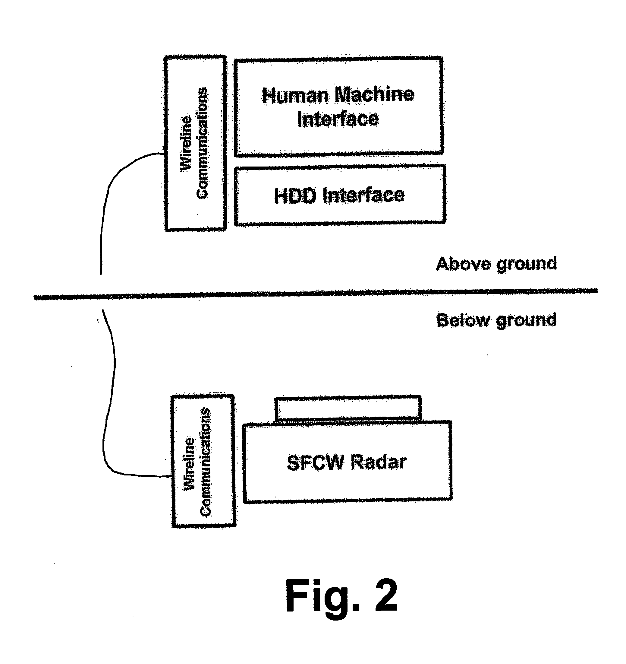
FIGS. 1 and 2 show conceptual diagrams of the obstacle avoidance radar system (OAS) of this invention. The basic components of the system, shown in FIG. 2, comprise the radar technology, which is disposed in the ground, a human machine interface and an HDD interface, which are disposed above ground, a communications link connecting the radar technology with the human machine interface and HDD interface, which allows communications and power to share a single conductor, and an antenna 12 (FIG. 1). In accordance with one preferred embodiment of this invention, the communications link comprises wireline connections. However, communications between the below ground and above ground system components may also be accomplished by means of wireless transmission or other communications systems apparent to those skilled in the art.

The application shown in FIG. 1 is for directional drilling and comprises radar electronics 10 mounted in the drill head 11 of a directional drill. The radar elect...


PUM


Abstract

An obstacle avoidance system for obstacle detection in an opaque material. The system includes at least one electromagnetic signal source adapted to produce an electromagnetic source signal suitable for transmission through the opaque material, at least one electromagnetic signal detector adapted to receive reflected electromagnetic energy signals from discontinuities in the opaque material encountered by the electromagnetic source signal, and a reflected electromagnetic energy signal processor suitable for determining a presence of obstructions and/or strata variations within the opaque material. The system is preferably integral with a head element suitable for traversing the opaque material, for example a subterranean drill bit.

Description

BACKGROUND OF THE INVENTION 1. Field of the Invention This invention relates to an electromagnetic sensing device. More particularly, this invention relates to an electromagnetic sensing device suitable for avoiding subterranean obstacles such as utility pipelines during underground operations such as drilling. Although not so limited, the system is particularly suitable for use in connection with Horizontal Directional Drilling (HDD) machinery. The system allows for the detection of underground utilities at a distance sufficient to allow the drill to avoid these obstacles. Although particularly suitable for use in directional drilling operations, it may be used in any application where space is limited and sensing of objects in opaque materials is required. The electromagnetic sensor design is a novel implementation of a stepped frequency continuous ground penetrating radar system designed to fit inside the drill head of a horizontal directional drill or in other applications whe...

Claims


Application Information

Patent Timeline
IPC IPC(8): E21B7/04E21B47/00
CPCE21B47/00E21B7/04E21B47/092
Inventor WILSON-LANGMAN, ALANINGGS, MICHAEL R.DU TOIT, LEENDERT JOHANNESKOTHARI, KIRANKUMAR M.HANSON, DAVID R.
Owner GAS TECH INST
Why Eureka
Try Eureka