Heating device and heating method

a heating device and heating method technology, applied in the direction of electrographic processes, instruments, manufacturing tools, etc., can solve the problems of heat energy loss caused by heat escaping, high standby power consumption of the heating device, and low heat supply performance of the heating device of the external heating type, so as to reduce the amount of heat lost, shorten the warm-up time, and reduce the effect of standby power consumption

a heating device and heating method technology, applied in the direction of electrographic processes, instruments, manufacturing tools, etc., can solve the problems of heat energy loss caused by heat escaping, high standby power consumption of the heating device, and low heat supply performance of the heating device of the external heating type, so as to reduce the amount of heat lost, shorten the warm-up time, and reduce the effect of standby power consumption

US20050061792A1Inactive Publication Date: 2005-03-24SHARP KK

Image

  • Heating device and heating method
  • Heating device and heating method
  • Heating device and heating method

Examples


Embodiment Construction

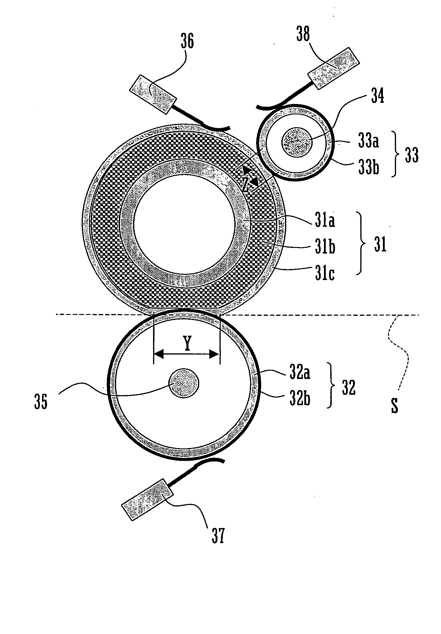
[0028] The following is a description with reference to FIGS. 1 through 10 of an embodiment of the present invention in which a heating device and a heating method of the present invention are applied to a fixing device provided in an electrophotographic image forming apparatus. Although the following embodiment describes a multi-color image forming apparatus, the present invention is suitable for use in an image forming apparatus comprising a single image forming station.

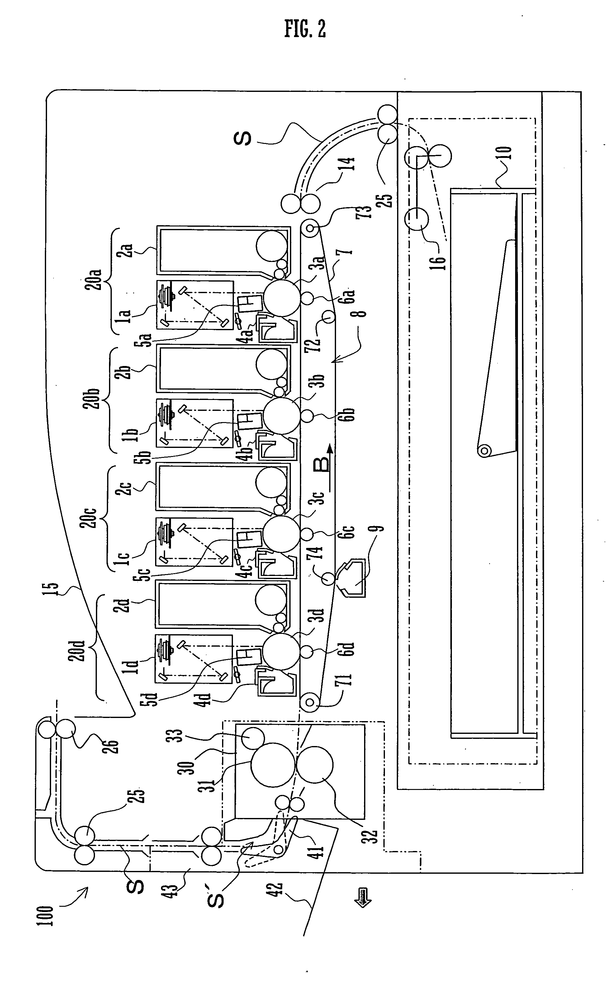
[0029]FIG. 2 illustrates configuration of an image forming apparatus 100 utilizing an electrophotographic process in which the heating device and heating method of the present invention are applied. The image forming apparatus 100 forms multi-color and monochromatic images on a paper sheet (including a sheet material such as a transfer or recording material) in accordance with image data supplied externally, as illustrated in FIG. 2.

[0030] The image forming apparatus 100 is provided with a paper transport path S ...


PUM

PropertyMeasurementUnit
diameteraaaaaaaaaa
temperatureaaaaaaaaaa
thicknessaaaaaaaaaa

Abstract

An upper heat roller with an external heat source and a lower heat roller with an internal heat source are arranged with a paper transport path therebetween, in such a manner as to be pressed against each other. The lower heat roller is heated sufficiently, thereby supplying a paper sheet with sufficient heat when the paper sheet is transported through a contact region between the upper and lower heat rollers to be heated.

Description

BACKGROUND OF THE INVENTION [0001] 1. Technical Field of the Invention [0002] The present invention relates to a heating device and a heating method applicable to: a fixing device provided in a dry electrophotographic apparatus; a drying device provided in a wet electrophotographic apparatus; a drying device provided in an inkjet image forming apparatus; an erasing device for rewritable media, etc. [0003] 2. Description of Related Art [0004] While there are several types of heating devices applicable to a fixing device provided in an electro-photographic image forming apparatus, a drying device provided in an inkjet image forming apparatus, and the like, an image forming apparatus of internal heating type is widely in use. Generally, the image forming apparatus of internal heating type is provided with a heat supplier as a heat source such as a halogen heater, inside a heating member such as a heat roller composed of a hollow metal core made of aluminum or the like. The surface of t...

Claims


Application Information

Patent Timeline
24 Mar 2005
Publication
US20050061792A1
IPC
G03G15/20; H05B1/02; H05B3/00
CPC
H05B1/0241; H05B3/0066; Y10T29/49083; G03G15/2039; Y10T29/49002; H05B3/0095
Inventors
KAGAWA, TOSHIAKI; YOKOTA, SHOGO