Mounting structure of electronic component, electro-optic device, electronic equipment, and method for mounting electronic component

a technology of electronic components and mounting structures, applied in the direction of dielectric characteristics, manufacturing tools, printed circuit non-printed electric components association, etc., can solve the problems of increasing the cost of acf b>22/, difficulty in providing conductive particles, and increasing production costs, so as to achieve high electrical reliability and improve production costs , the effect of increasing the reliability of electrical components

Active Publication Date: 2005-03-24
BOE TECH GRP CO LTD
View PDF8 Cites 48 Cited by
  • Summary
  • Abstract
  • Description
  • Claims
  • Application Information

AI Technical Summary

Benefits of technology

As described above, a bump electrode including a core composed of an elastic inner resin and conductive film covering the surface of the core is used in an exemplary aspects of the present invention. Exemplary aspects of the present invention provide a mounting structure of an electronic component having high electrical reliability with a low production cost. The electrical reliability is further enhanced by controlling the elastic deformation Δt of the bump electrode with high accuracy.

Problems solved by technology

In general, however, it is very difficult to provide the conductive particles 22a with a sufficient amount of elastic deformation so as to enhance the reliability of the conductive connection.
This increases the cost of the ACF 22, and therefore, increases the production cost.
In addition, since it is more difficult to provide the conductive particles 22a with sufficient elastic deformation, providing electrical reliability during a temperature change becomes difficult.
Furthermore, in the above method using the conductive particles composed of a conductive rubber, it is more difficult to form the conductive rubber having a fine diameter so as to match with the above-described small pitch.
Unfortunately, this method further increases the production cost.

Method used


Image

  • Mounting structure of electronic component, electro-optic device, electronic equipment, and method for mounting electronic component
  • Mounting structure of electronic component, electro-optic device, electronic equipment, and method for mounting electronic component
  • Mounting structure of electronic component, electro-optic device, electronic equipment, and method for mounting electronic component

Examples


Embodiment Construction

Mounting Structure of Electronic Component and Electro-Optic Device

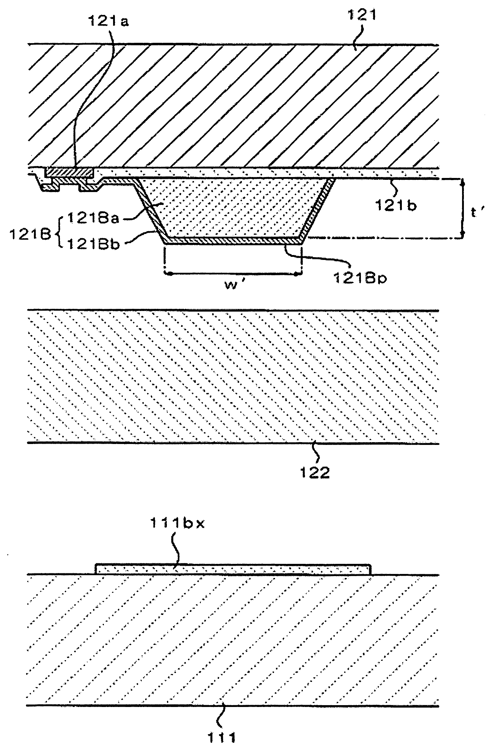
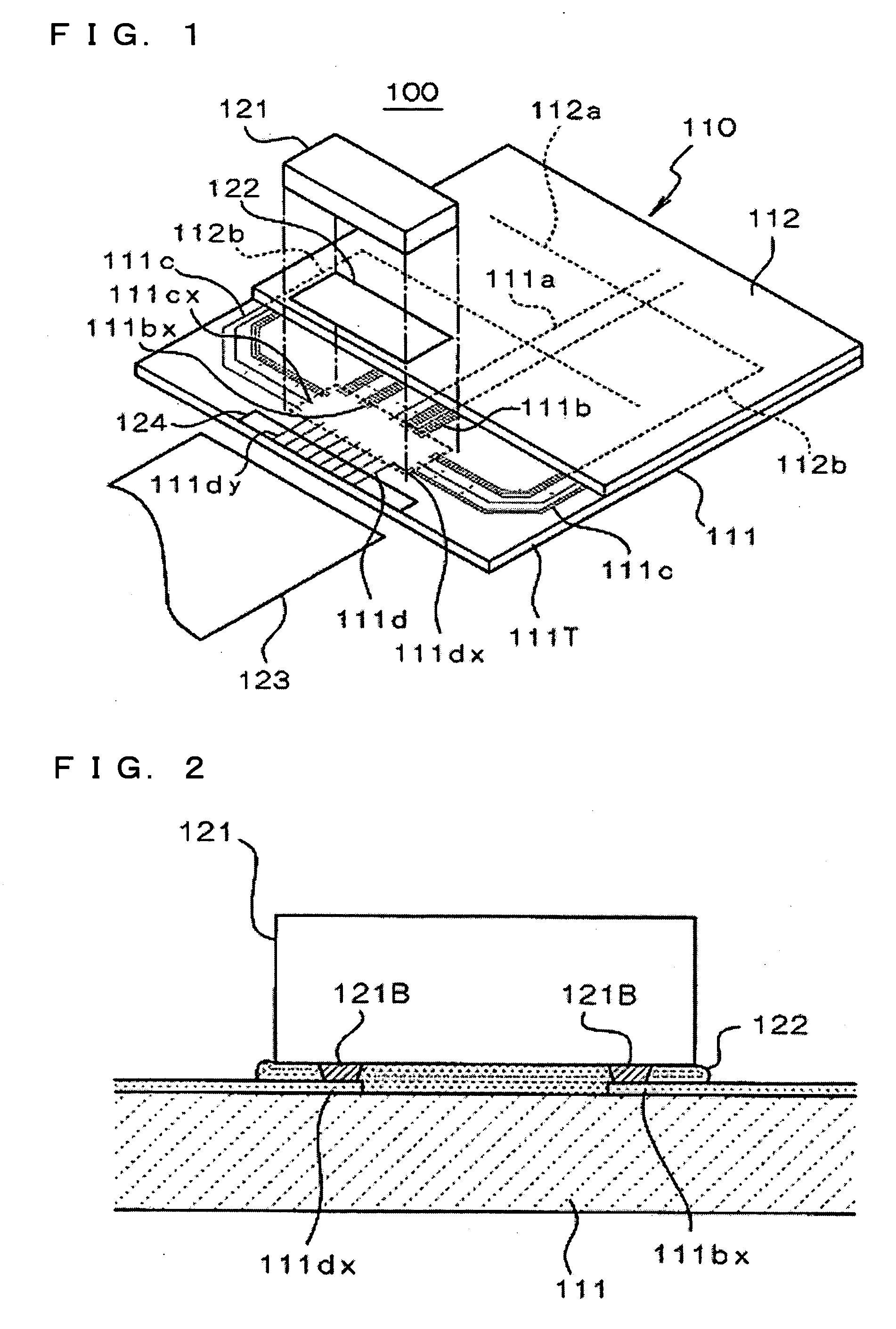
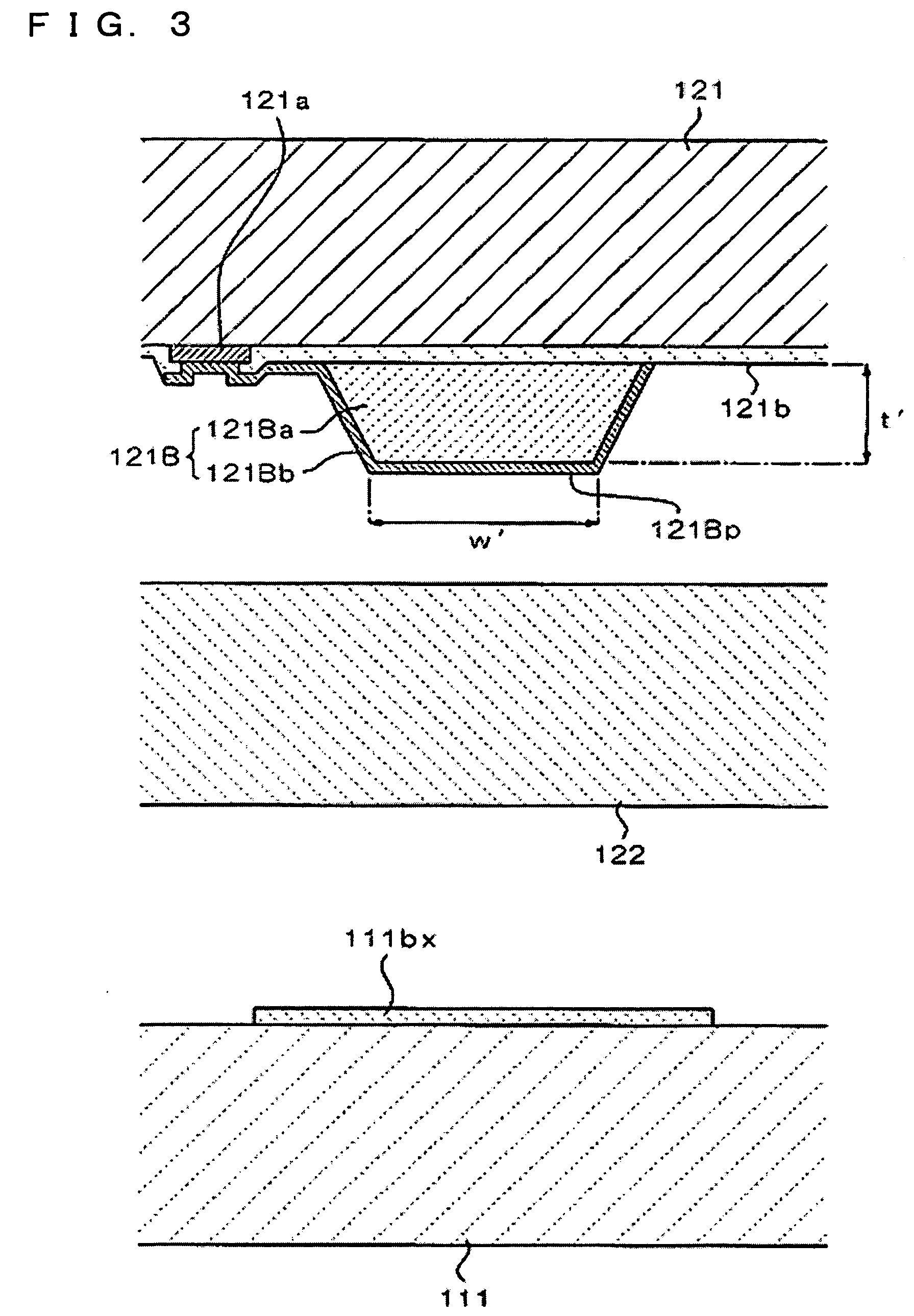
Examples of the present invention will be described with reference to drawings. FIG. 1 is a schematic showing a liquid crystal display device that is an exemplary embodiment of a mounting structure of an electronic component and an electro-optic device according to the present invention.

A liquid crystal display device 100 shown in the figure includes a liquid crystal panel 110 and an electronic component (liquid crystal-driving IC chip) 121. Additional components, such as a polarizer, a reflective sheet, and a backlight (not shown in the figure) are disposed according to need.

The liquid crystal panel 110 includes substrates 111 and 112 composed of, for example, glass or a plastic. The substrate 111 and the substrate 112 are disposed facing each other and bonded with, for example, a sealing member (not shown in the figure). A liquid crystal (not shown in the figure), which is an electro-optic material, is fille...


PUM

PropertyMeasurementUnit
temperatureaaaaaaaaaa

Abstract

To provide a low cost mounting structure of an electronic component and to increase the reliability of the conductive connection between a bump electrode and a terminal formed on a substrate, in the mounting structure of the electronic component, the bump electrode includes a core composed of an inner resin and a conductive film covering the surface of the core. The bump electrode is brought into conductive contact with the terminal directly and is elastically deformed to make contact with the face of the substrate in a planar manner. A sealing resin is filled in around the conductive contact portion between the bump electrode and the terminal to hold the bump electrode and the terminal.

Description

BACKGROUND OF THE INVENTION 1. Field of Invention Exemplary aspects of the present invention relate to a mounting structure of electronic components, electro-optic devices, electronic equipment, and a method for mounting electronic components, and in particular, to a mounting structure and a method for mounting in which an electronic component having bumps is mounted on terminals composed of a transparent conductor formed on a glass substrate. 2. Description of Related Art A related art technology for mounting an electronic component, such as a semiconductor IC, has been used in a circuit board that is installed in-various kinds of electronic equipment or a liquid crystal display device. For example, a related art liquid crystal-driving IC chip to drive a liquid crystal panel is mounted in a liquid crystal display device. This liquid crystal-driving IC chip is directly mounted on a glass substrate in the liquid crystal panel. Alternatively, this liquid crystal-driving IC chip is...

Claims


Application Information

Patent Timeline
Patent Type & Authority Applications(United States)
IPC IPC(8): H05K3/28H01B1/24H01L21/60H01L23/498H05K1/18H05K3/30H05K3/32
CPCH01L23/49816H01L2924/12044H05K3/305H05K3/325H05K2201/0133H05K2201/10674H05K2201/10977H01L2924/07811H01L2224/2929H01L2224/293H01L2224/73204H01L2224/83851H01L2924/00H01B1/24
Inventor SAITO, ATSUSHITANAKA, SHUICHI
Owner BOE TECH GRP CO LTD
Why Eureka
Try Eureka