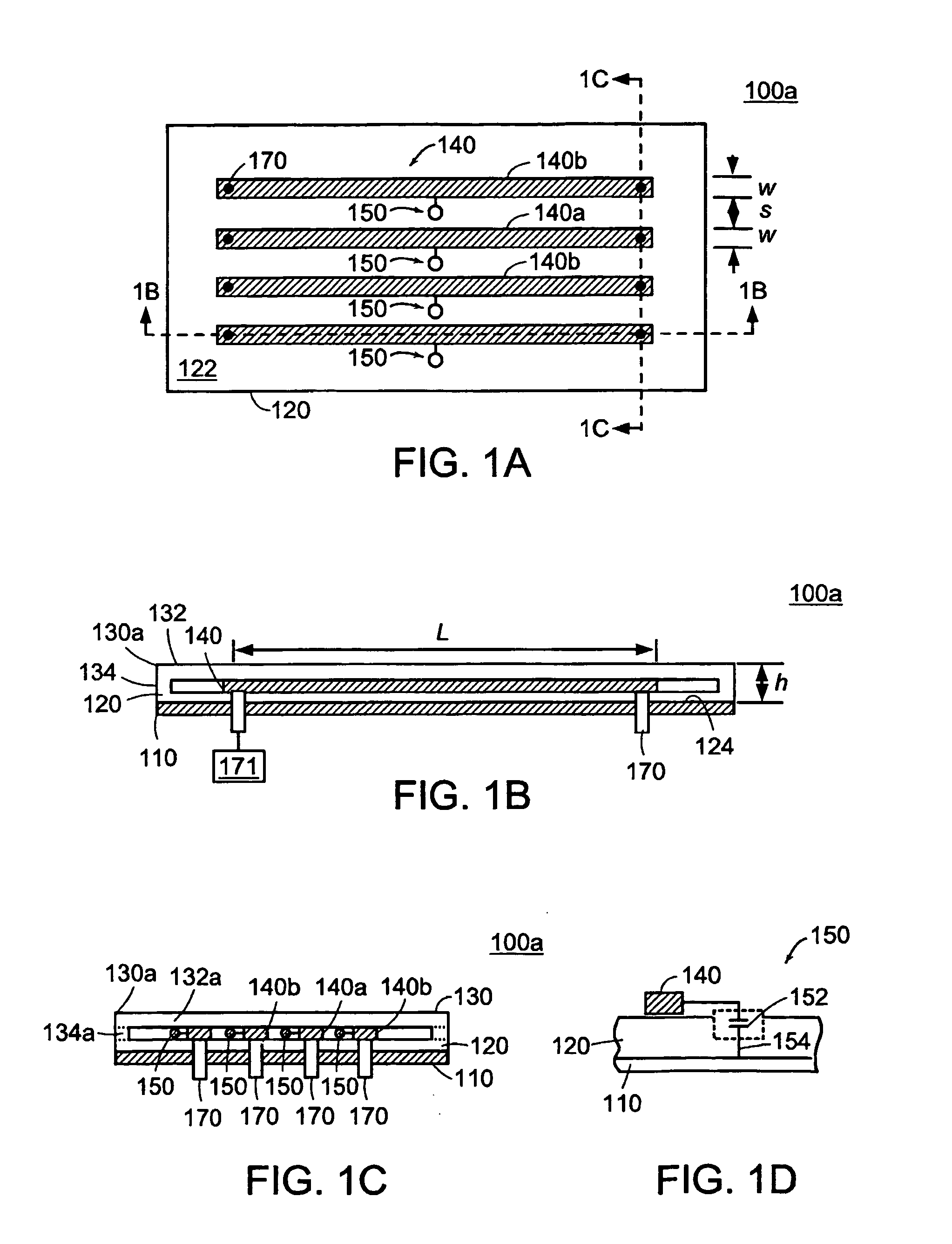
[0017] The detection device includes a strip array antenna including at least one, and preferably a plurality of conductors being arranged so as to be generally parallel to each other and a plurality of
reactive components or elements, such
reactive components or elements including for example a
capacitor, an
inductor or both. At least one of the plurality of
reactive components is electrically coupled to each conductor and to one of ground or a
virtual ground. Each of the conductors has a length and each of the reactive components has a
value set so that the combination of the conductor length and the
reactance of the reactive component is such as to substantially reduce the
coupling of a
signal in one of the conductors to an adjacent conductor.
[0018] More particularly, the
reactance value of the reactive component value is set or tuned so that the effective
electrical length of each conductor is substantially equal to be about nλ / 4, where n is an integer ≧1 and λ is the EM
wavelength of the
signal to be detected by each conductor in combination with the at least one reactive component. For MRI applications, A is the
wavelength corresponding to the NMR frequency for the nuclei being subjected to a given
magnetic field strength by the main or primary magnetic coils. For example, the quarter wavelength for a
proton NMR in a 1.5 Telsa
magnetic field in air is about 117 cm, which reduces to about 46 cm in a glass
dielectric PSA (see Lee et al, Magn Reson Med 2001; 45: 673-683), and is effectively reduced and / or adjusted further in the conductor strips of the present invention through the use of the reactive components.
[0019] In a more particular embodiment, the length of each conductor also is established so as to optimize the NMR performance of the array for the particular geometry and size of the sample, sub-region of the sample,
region of interest or organ to be imaged and the strip array antenna is configured and arranged so as to substantially reduce coupling of signals between adjacent conductors. In this way, the conductor length is set so NMR performance is optimized for the
region of interest through the use of the reactive component, whose values are set such as to tune the chosen length of the conductor so as to be electrically equal to about nλ / 4, to thereby substantially reduce signal coupling. Thus, and in an exemplary embodiment, the length of the conductor can be reduced so as to be on the order of from about 10 to 30 cm, dimensions that are comparable to the body or depth of specific organs of interest, while the
reactance of the reactive components is used to tune the length of each conductor so as to be electrically equal to about nλ / 4.
[0020] In another more particular embodiment, the length of each conductor is established so as to optimize the signal-to-
noise ratio (SNR) over a desired range in an area or
region of interest, and the strip array antenna also is configured and arranged so as to substantially reduce coupling of signals between adjacent conductors. In this way, the conductor length can be set so the SNR is optimized for the region of interest through the use of the reactive component(s), whose values are set such as to tune the length of the conductor so as to be electrically equal to about nλ / 4 with a geometry configured to substantially reduce signal coupling.
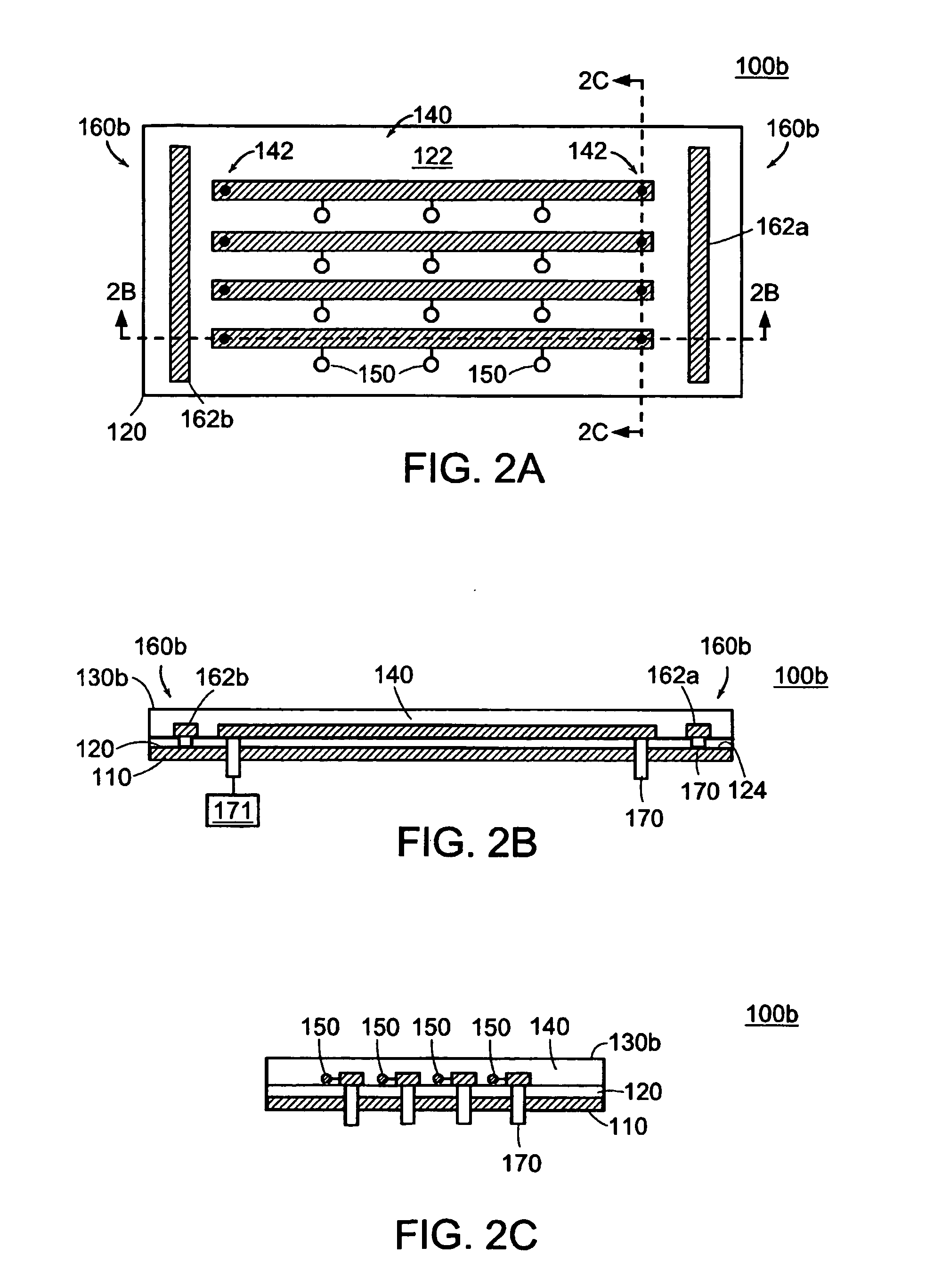
[0034] In yet another embodiment, the detection device is configurable so as to include a conducting electromagnetic (EM) interference guard that is electrical connected in a fashion so that the guard substantially electrically isolates at least a portion of each conductor (e.g., the ends of the conductors) from the environment including areas of the imaged object outside of the specific area being scanned and other conducting surfaces that may be present. In one embodiment, the EM guard includes two conducting guard strips, each guard strip being disposed proximal the ends of each conductor and insulated from the tuned conductors that form the
detector elements, so as to minimize EM from the environment. In a more specific embodiment, a
long axis for each of the guard strips extends generally perpendicular to a
long axis of each conductor.
[0035] In another embodiment, a plurality of guard strips are arranged about the periphery of the plurality of conductors that form the
detector elements so as to, in effect enclose both the ends and sides of the plurality of conductors. In yet another embodiment, the EM guard comprises one or more members that are configured so as to provide any of a number of geometrical shapes such as circular and oval. These one or more members are formed about the ends or about the periphery of the plurality of conductors such that the configuration minimizes external
EM coupling or interactions.

