Small size antenna, surface mounting type antenna and antenna device as well as radio communication device

Inactive Publication Date: 2005-03-24
KYOCERA CORP
View PDF9 Cites 11 Cited by
  • Summary
  • Abstract
  • Description
  • Claims
  • Application Information

AI Technical Summary

Benefits of technology

[0047] The wireless communication device according to the present invention that is formed as described above is provided as a small size and highly functional wireless communication device that can deal with two frequencies by using one surface mounting type antenna or antenna device.
[0048] As described above, according to the present invention, a surface mounting type antenna that can deal with two frequen

Problems solved by technology

It becomes necessary to scrap the board 4 together with the antenna, though this is economically disadvantageous, in the case where the properties of the antenna are found to be defective as a result of quality management where the frequency properties are measured after the antenna has been secured to the board 4 by means of the solders 3.
However, in the case where measurement is carried out without utilizing the solder 3, as shown in FIG. 8B, a gap occurs between the board 4 and the conductor 2 due to the protrusion 23 and a problem arises where the frequency becomes different from that of the case where measurement is carried out when the antenna is secured to the board by using the solder 3.
In addition, in the case where the base 13 in rectangular parallelepiped is utilized, a problem arises where chipping occurs when bases 13 collide into each other during the manufacturing process for bases 13 in rectangular parallelepiped form or during the process for forming conductors 2 or base 13 collides into a jig or the like that is utilized during the manufacturing process.
In the case where chipping has occurred, the product might become defective judging from the appearance and at the same time, in the case where chipping has occurred to a portion of the conductor 2, the product loses the function as an antenna due to the occurrence of disconnection.
A problem arises where some products lack the properties required for an antenna as a result of the occurrence of an electrically insufficient connection when the connection i

Method used


Image

  • Small size antenna, surface mounting type antenna and antenna device as well as radio communication device
  • Small size antenna, surface mounting type antenna and antenna device as well as radio communication device
  • Small size antenna, surface mounting type antenna and antenna device as well as radio communication device

Examples


Example

Embodiment 1

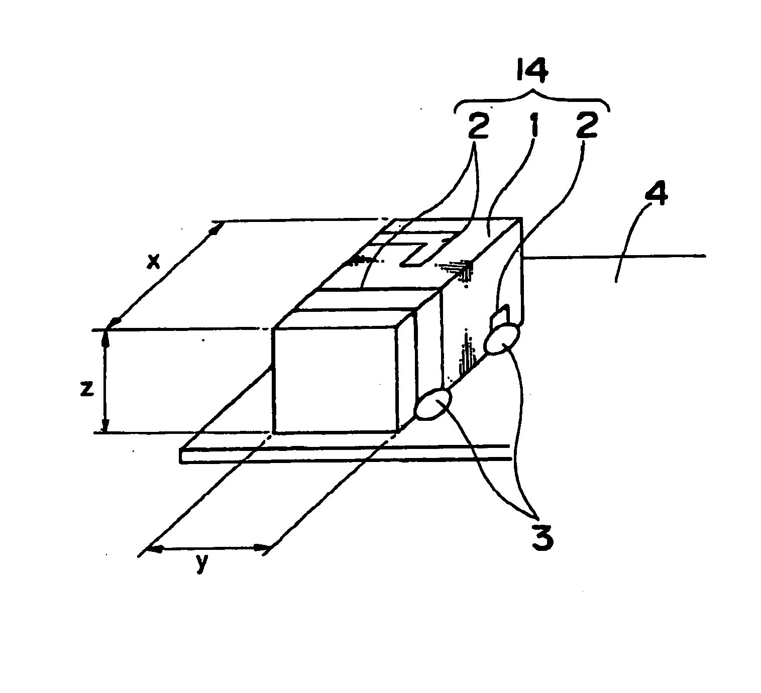
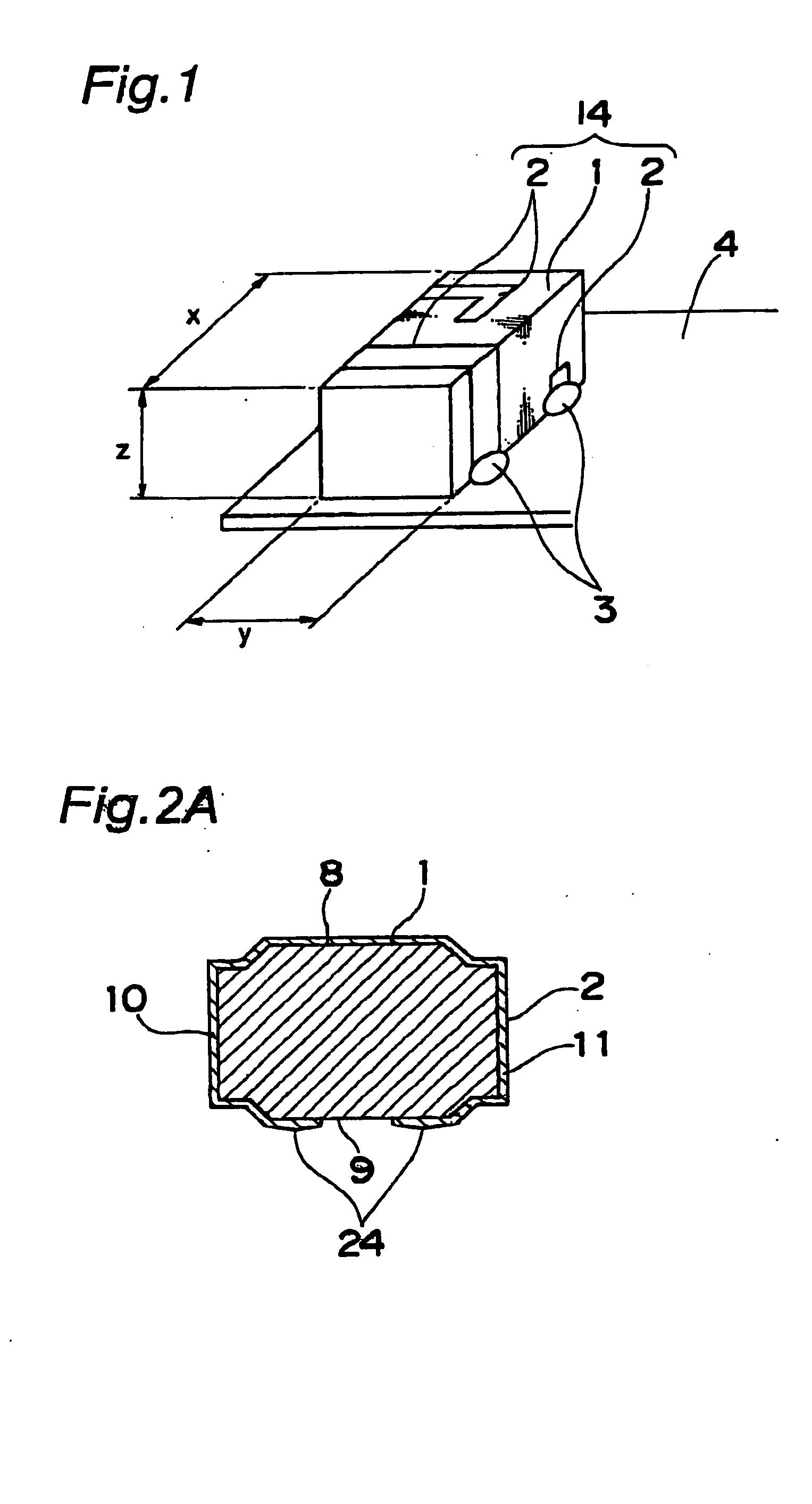
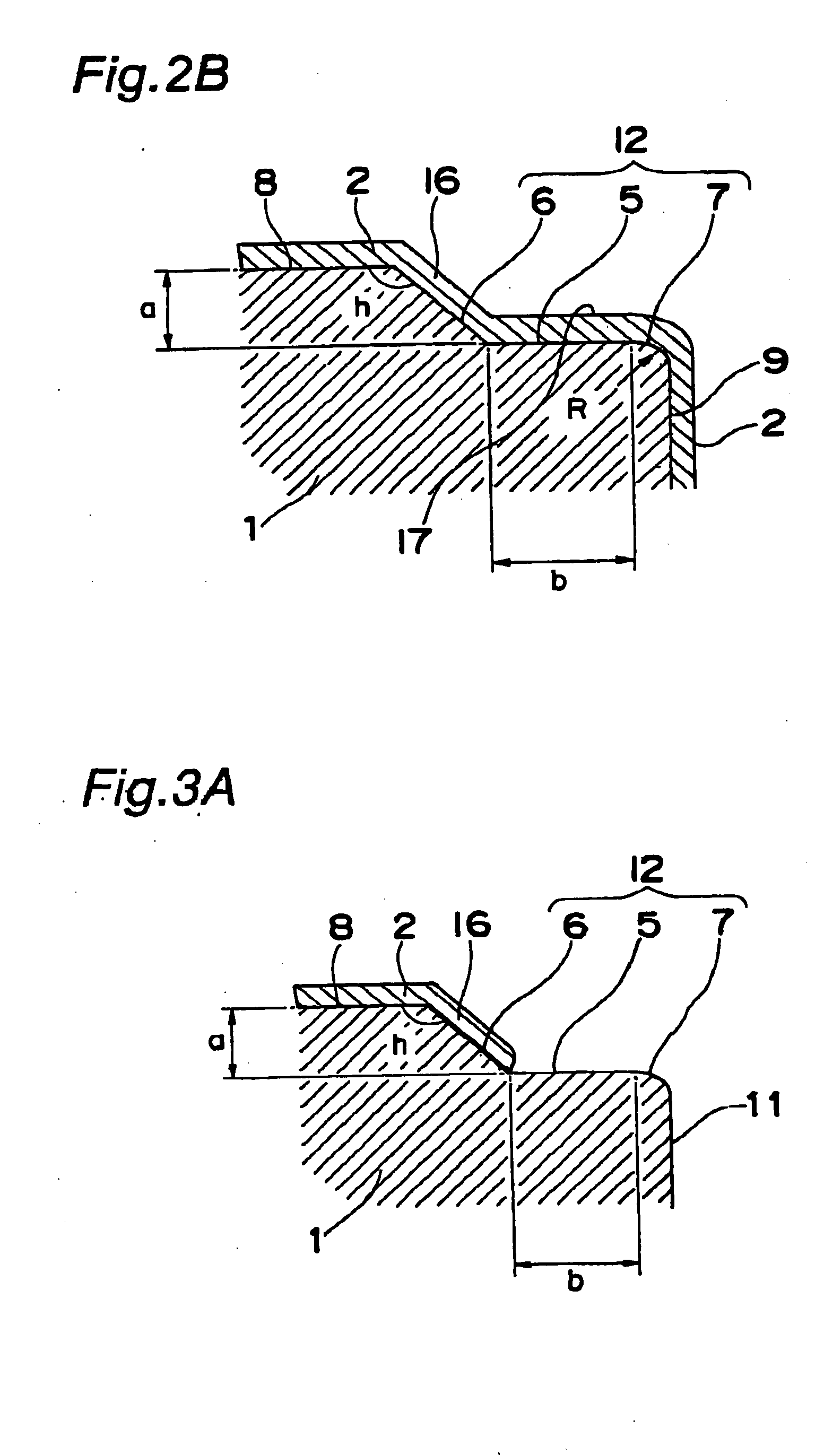
[0072]FIG. 1 is a perspective view schematically showing the configuration of a small size antenna according to Embodiment 1 of the present invention, FIG. 2A is a cross-sectional view in the longitudinal direction showing the same, and FIG. 2B is an enlarged cross-sectional view showing a portion of FIG. 2A.

[0073] As shown in FIGS. 1, 2A and 2B, a small size antenna 14 of the present invention is made of dielectric ceramics, where conductors 2 are formed of at least two adjoining sides of base 1 in rectangular parallelepiped form in a sequential manner. Here, one end of each conductor 2 is used as a feeding terminal for applying a voltage, and is connected to a feeding electrode that is formed on a mounting surface of a board 4 by means of a solder 3.

[0074] The base 1 is made of Ba—Nd—Ca—Ti based dielectric ceramics (of which the relative dielectric constant is 80 to 120), Nd—Al—Ca—Ti based dielectric ceramics (of which the relative dielectric constant is 43 to 46), ...

Example

Embodiment 2

[0093]FIG. 9 is a perspective view of a first antenna device according to Embodiment 2 of the present invention, and the first antenna device of Embodiment 2 is formed of a first surface mounting type antenna 101 and a mounting substrate 112 on which this surface mounting type antenna 101 is mounted.

[0094] In addition, the first surface mounting type antenna 101 is formed of a base 107 in rectangular parallelepiped form made of dielectrics or a magnetizer, and of first to fourth radiation electrodes formed on the base 107 as described below.

[0095] The first radiation electrode 102 is formed on a first side (the lower surface of the base 107 in FIG. 9) of the base 107.

[0096] The second radiation electrode 104 is formed on a second side (the upper surface of the base 107 in FIG. 9) that faces the first side of the base 107.

[0097] The third radiation electrode 103 is formed on a third side (the back side of the base 107 in FIG. 9) in the proximity of a first end surfac...

Example

Embodiment 3

[0121]FIG. 10 is a perspective view of a second antenna device according to Embodiment 3 of the present invention, and the second antenna device of this Embodiment 3 is formed of a second surface mounting type antenna 121 and a mounting substrate 132 on which the antenna 121 is mounted.

[0122] The second surface mounting type antenna 121 according to the present Embodiment 3 is formed of a base 127 in rectangular parallelepiped form made of dielectrics or a magnetizer, and of first to fourth radiation electrodes which are formed on the base 127 in the below described manner.

[0123] Here, in Embodiment 3, first to fourth sides of the second surface mounting type antenna 121 are defined as follows. That is to say, the side that faces the mounting substrate 132 is referred to as the fourth side, the side that faces the fourth side is referred to as the third side, the side that is closer to the grounding conductive layer 133 of the two sides between the fourth side and the...


PUM


Abstract

In order to provide a small size antenna where excellent antenna properties can be stably gained, a frequency adjustment is easy and a simple measurement is possible, according to the present invention, a small size antenna formed of a conductor of at least two adjoining surfaces of a base in rectangular parallelepiped form made of dielectric ceramics is characterized in that: a step is made of a flat portion parallel to one surface of the two adjoining surfaces and an inclining portion located between the one surface and the flat portion, in a corner portion of the two surfaces on which the conductor is formed; the width of the flat portion is 0.08 mm or less; and a border portion between the flat portion and the other surface of the two adjoining surfaces is a curve having a curvature radius R of 0.03 mm to 0.2 mm.

Description

BACKGROUND OF THE INVENTION [0001] 1. Field of the Invention [0002] The present invention relates to a surface mounting type small size antenna that is used in the communication field, particularly used by being incorporated in mobile communication equipment such as cellular phones and, in particular, relates to a small size surface mounting antenna and an antenna device which deal with double channels as well as a radio communication device using the same. [0003] 2. Description of the Related Art [0004] In recent years, miniaturization of mobile communication equipment such as cellular phones has made rapid progress. Together with the miniaturization of such communication equipment, antennas which are incorporated in communication equipment are also required to be miniaturized and a small size antenna where a conductor is formed on the surface of a base in rectangular parallelepiped form so that the antenna is mounted on the surface of an internal board of communication equipment h...

Claims


Application Information

Patent Timeline
IPC IPC(8): H01Q1/22H01Q1/24H01Q1/36H01Q1/38H01Q5/10H01Q5/371H01Q9/04H01Q9/40H01Q13/08H01Q21/30
CPCH01Q1/2283H01Q1/243H01Q5/364H01Q21/30H01Q1/38H01Q13/08H01Q1/24
Inventor FURUNO, TSUYOSHIWATADA, KAZUOHAMADA, KOJIMURAKAWA, SHUNICHI
Owner KYOCERA CORP
Why Eureka
Try Eureka