Tuned perturbation cone feed for reflector antenna

Active Publication Date: 2005-03-24
COMMSCOPE TECH LLC
View PDF8 Cites 39 Cited by
  • Summary
  • Abstract
  • Description
  • Claims
  • Application Information

AI Technical Summary

Problems solved by technology

This configuration also facilitates the mounting of an “Outdoor Unit” comprising the initial stages of a transceiver system, directly onto the back of the main reflector and also eliminates the need for a separate feed support structure that would conventionally span the face of the main reflector, thereby introducing som

Method used


Image

  • Tuned perturbation cone feed for reflector antenna
  • Tuned perturbation cone feed for reflector antenna
  • Tuned perturbation cone feed for reflector antenna

Examples


Embodiment Construction

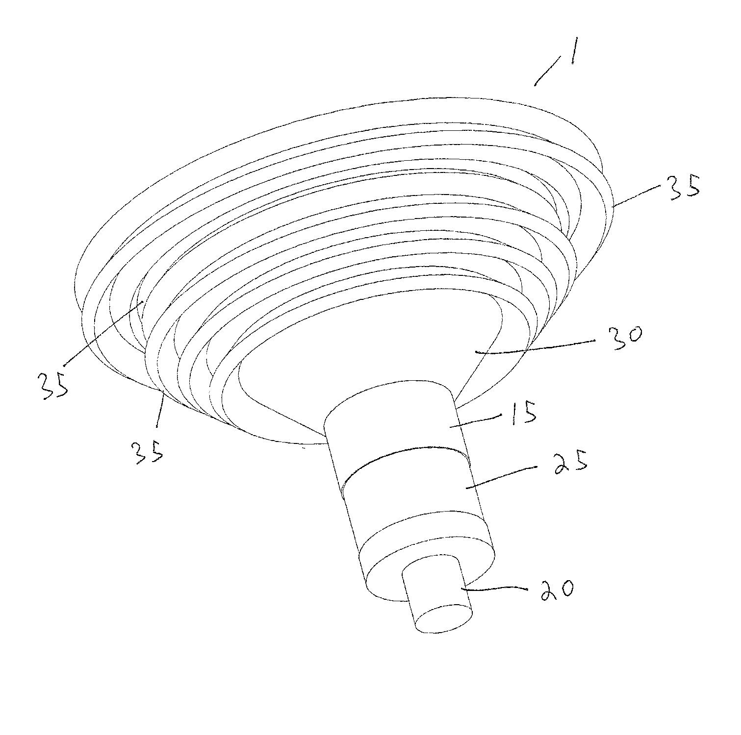
[0053] The self-supported feed system described herein integrates the waveguide transmission line, aperture and sub-reflector into a single assembly comprising a length of waveguide, the aperture of which is terminated with a corrugated dielectric cone sub reflector assembly, the front and back surfaces of which are geometrically shaped and corrugated to provide a desired amplitude and phase radiation pattern suitable for efficient illumination of the main reflector profile.

[0054] A typical dual reflector antenna according to the invention is shown in FIGS. 4a and 4b. The sub-reflector assembly 1 is mounted on and supported by a waveguide 2 to position the sub-reflector assembly 1 proximate a focal point of the dish reflector 3, here shown as a dish reflector 3 having a “deep dish” configuration.

[0055] Details of the sub-reflector 1 assembly according to the invention will now be described in detail. A first embodiment of a sub-reflector 1 according to the invention is shown in FI...


PUM


Abstract

A sub-reflector for a dish reflector antenna with a waveguide supported sub-reflector. The sub-reflector formed from a dielectric block, concentric about a longitudinal axis. The dielectric block having a first diameter waveguide junction portion adapted for coupling to an end of the waveguide and a sub-reflector surface coated with an RF reflective material having a periphery with a second diameter larger than the first diameter. A leading cone surface extends from the waveguide junction portion to the second diameter at an angle. The sub-reflector surface and the leading cone surface having a plurality of non-periodic perturbations concentric about the longitudinal axis.

Description

BACKGROUND OF INVENTION [0001] 1. Field of the Invention [0002] This invention relates to microwave dual reflector antennas typically used in terrestrial point to point, and point to multipoint applications. More particularly, the invention provides a low cost self supported feed solution for use in frequency bands between 5 GHz and 60 GHz wherein stringent regulatory standard compliance and or specific system electrical characteristics are required. The invention is particularly suited to “deep dish” designs overcoming performance limitations of prior art devices and obviating the need for a conventional shroud assembly. It is also applicable to more conventional dish profiles. [0003] 2. Description of Related Art [0004] Dual reflector antennas employing self-supported feed direct a signal incident on the main reflector onto a sub-reflector mounted adjacent to the focal region of the main reflector, which in turn directs the signal into a waveguide transmission line typically via a...

Claims


Application Information

Patent Timeline
IPC IPC(8): H01Q13/02H01Q19/19
CPCH01Q19/193H01Q13/0216
Inventor HILLS, CHRIS
Owner COMMSCOPE TECH LLC
Why Eureka
Try Eureka