Temperature measurement and heat-treating metods and system
a technology of temperature measurement and heat treatment, applied in the field of methods and systems for temperature measurement, can solve the problems of significant temperature measurement errors, inability to accurately directly measure, and conventional techniques cannot produce sufficiently shallow junctions to meet the requirements
- Summary
- Abstract
- Description
- Claims
- Application Information
AI Technical Summary
Benefits of technology
Problems solved by technology
Method used
Image
Examples
first embodiment
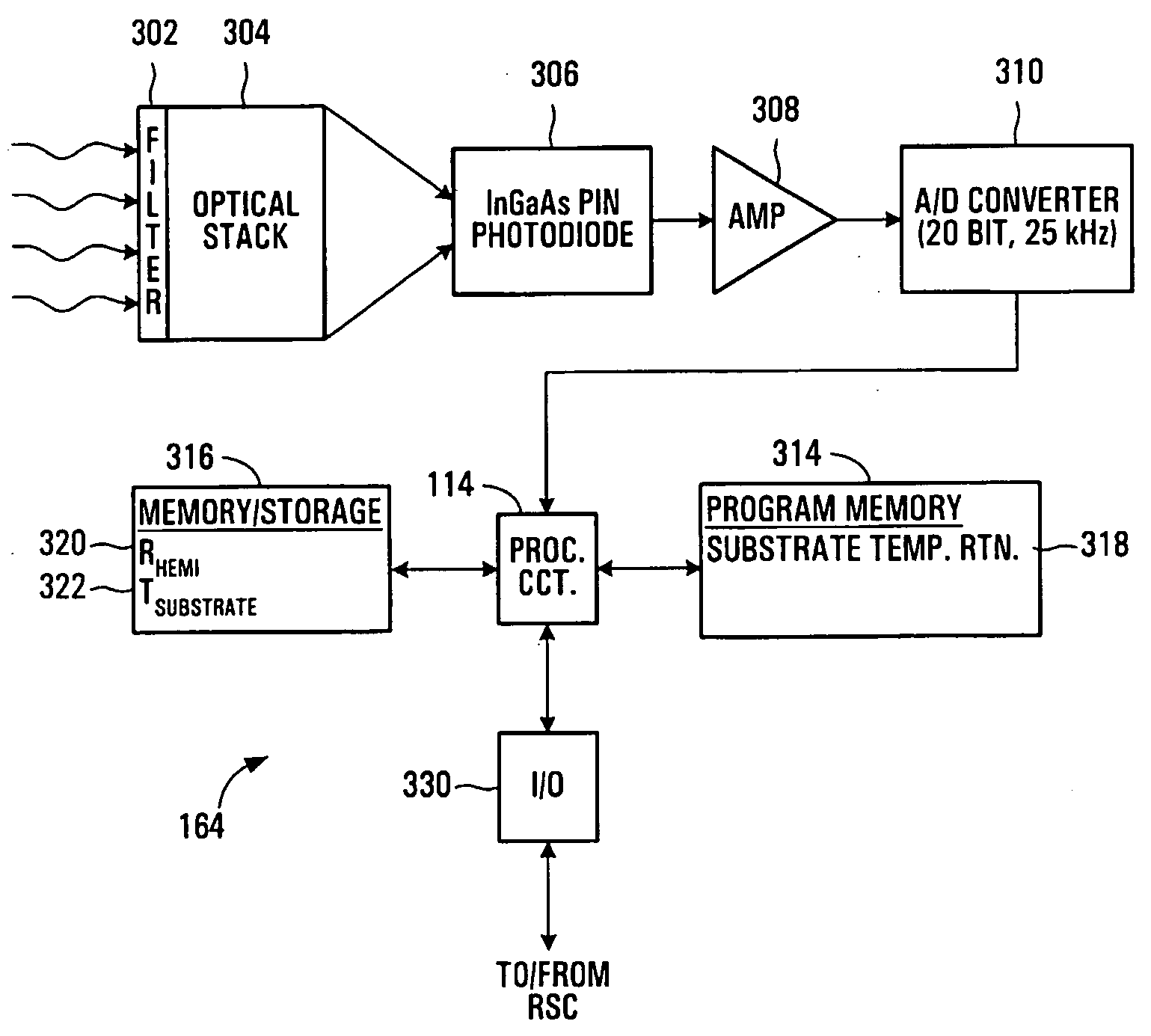
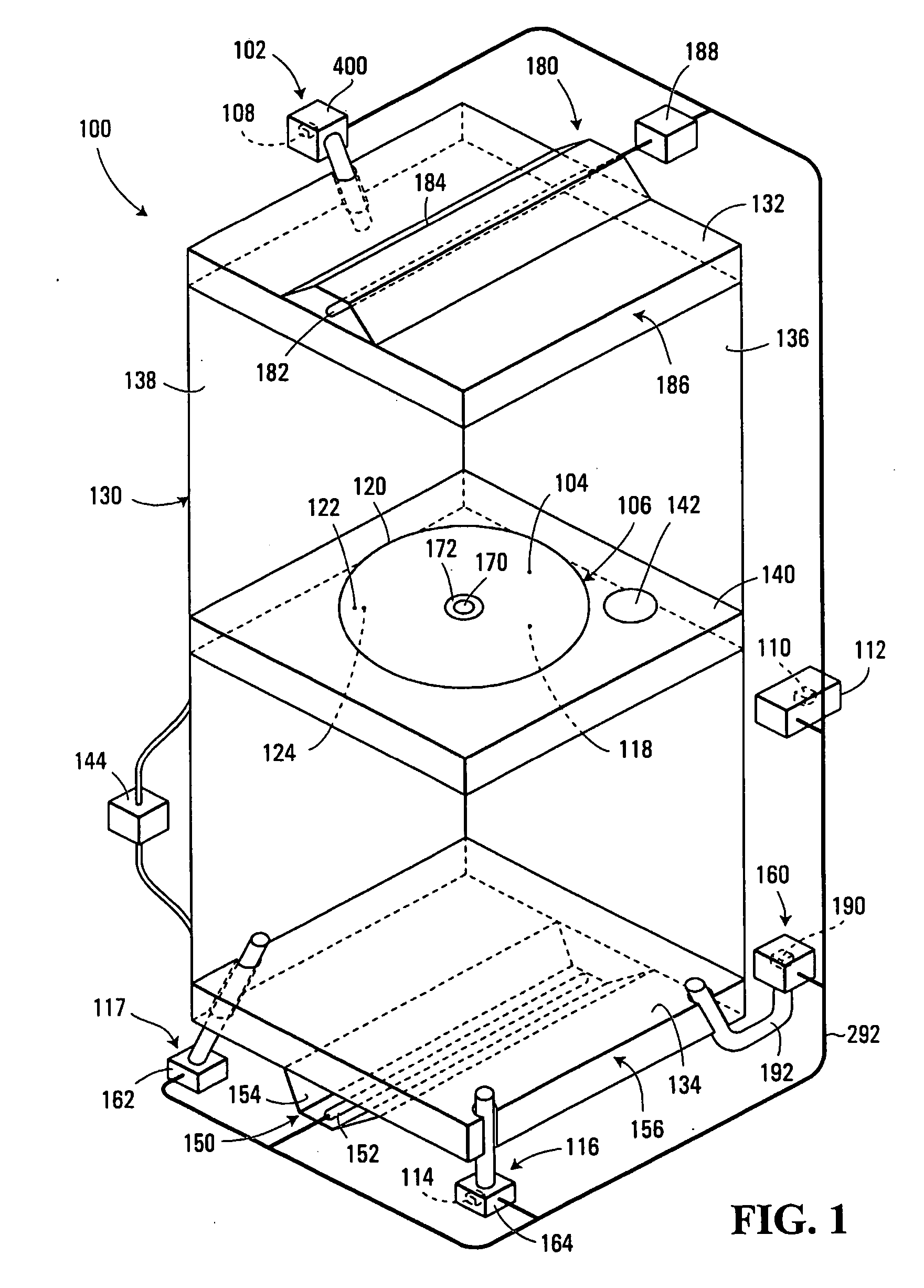
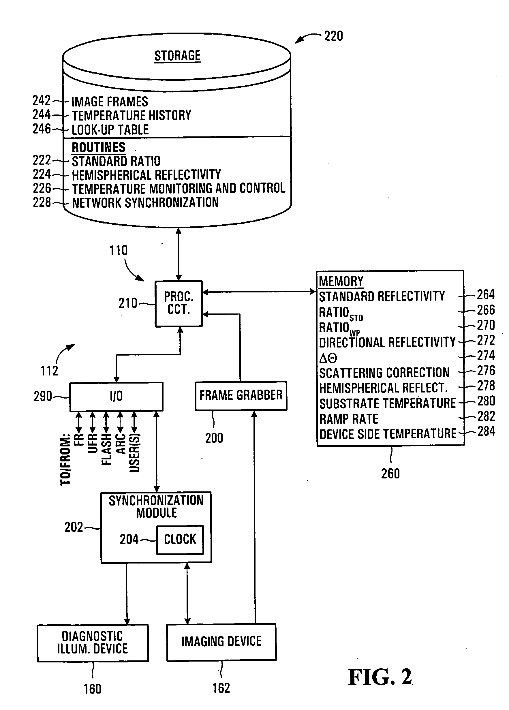
Referring to FIG. 1, a temperature measurement system according to the invention is shown generally at 100. In this embodiment, the system 100 includes a measurement device 102 configured to measure a present intensity of radiation thermally emitted from a first surface 104 of a workpiece 106. The system 100 further includes at least one processor circuit in communication with the measurement device 102. The at least one processor circuit is configured to identify a present temperature of the first surface 104, in response to the present intensity and at least one previous thermal property of the first surface at a respective previous time.
In this embodiment, the at least one processor circuit includes a processor circuit 108. In the present embodiment, the processor circuit 108 is located within a housing of the measurement device 102, although alternatively, the processor circuit may be located remotely from the measurement device if desired. In this embodiment, the at least one ...
second embodiment
For example, referring to FIG. 11, a power control circuit of the power control system 188 according to the invention is shown generally at 970. The capacitor bank that is to be discharged to produce the irradiance flash is again symbolically shown as a single capacitor 962, for ease of illustration. Along a first electrical pathway 972 connecting one plate of the capacitor 962 to one electrode of the flash lamp, a switch 974 and an inductor 976 are interposed in series. A second electrical pathway 978 connects the other plate of the capacitor to the other electrode of the flash lamp. A resistor 980 and a second switch 982 in series, are connected between the first electrical pathway 972 and the second electrical pathway 978, with the resistor being connected to the first electrical pathway 972 at a point 984 between the first switch 974 and the inductor 976, and the second switch 986 being connected to the second electrical pathway 978 at a point 986. The second switch 982 may incl...
third embodiment
Similarly, referring to FIG. 12, a power control circuit of the power control system 188 according to the invention is shown generally at 990. The capacitor bank that is to be discharged to produce the irradiance flash is again symbolically shown as a single capacitor 962, for ease of illustration. Along a first electrical pathway 991 connecting a first plate of the capacitor 962 to a first electrode of the flash lamp 182, a first switch 992, a first inductor 993, and a second inductor 994 in parallel with a second switch 995, are interposed in series. In this regard, the second switch 995 is interposed along an electrical sub-pathway 996 of the first electrical pathway 991. One end of the electrical sub-pathway 996 is connected to a point 997 interposed between the first inductor 993 and the second inductor 994. The other end of the electrical sub-pathway 996 is connected to a point 998 interposed between the second inductor 994 and the first plate of the flash lamp 182. The second...
PUM
 Abstract
Description
Claims
Application Information
 - R&D
- Intellectual Property
- Life Sciences
- Materials
- Tech Scout
- Unparalleled Data Quality
- Higher Quality Content
- 60% Fewer Hallucinations
Browse by: Latest US Patents, China's latest patents, Technical Efficacy Thesaurus, Application Domain, Technology Topic, Popular Technical Reports.
© 2025 PatSnap. All rights reserved.Legal|Privacy policy|Modern Slavery Act Transparency Statement|Sitemap|About US| Contact US: help@patsnap.com


