System and method for defective detector cell and DAS channel correction

a detector cell and defect technology, applied in the field of imaging systems and image accuracy, can solve the problems of increasing the probability of failure in the detector cell, das channel, or das application-specific integrated circuit (asic) failure, and the detection of internal defects in objects, so as to minimize the impact and minimize the number of artifacts.

Active Publication Date: 2005-03-24
GENERAL ELECTRIC CO +1
View PDF4 Cites 57 Cited by
  • Summary
  • Abstract
  • Description
  • Claims
  • Application Information

AI Technical Summary

Benefits of technology

Certain embodiments of the present invention provide a method and system for minimizing an impact of a malfunctioning cell by using other signals within the malfunctioning cell's projection view to minimize the number of artifacts which may be observed. A detector row in an array may have a malfunctioning cell in a channel and a projection view. An estimate for a malfunctioning cell's missing projection sample may be interp

Problems solved by technology

For instance, internal defects in an object may be detected.
As a number of detector cells and DAS channels increases, a probability of failure in a detector cell, DAS channel, or DAS application-specific integrated circuit (ASIC) failure increases.
A problem in any one detector cell in either the detector or the DAS channel may cause artifacts in the reconstructed images.
Any inaccuracies or “artifacts” in the image produced by the imaging system or cells in the imaging system may result in actions taken by physicians, medical practitioners or other observers based on incorrect information.
As a result, a probability of a malfunctioning cell increases.
Replacement of a malfunctioning cell significantly increases the cost of a system.
Replacing all failed components on a system with a large number of detector channels may not be economical.
In addition, failed components interrupt the operation flow in a

Method used


Image

  • System and method for defective detector cell and DAS channel correction
  • System and method for defective detector cell and DAS channel correction
  • System and method for defective detector cell and DAS channel correction

Examples


Embodiment Construction

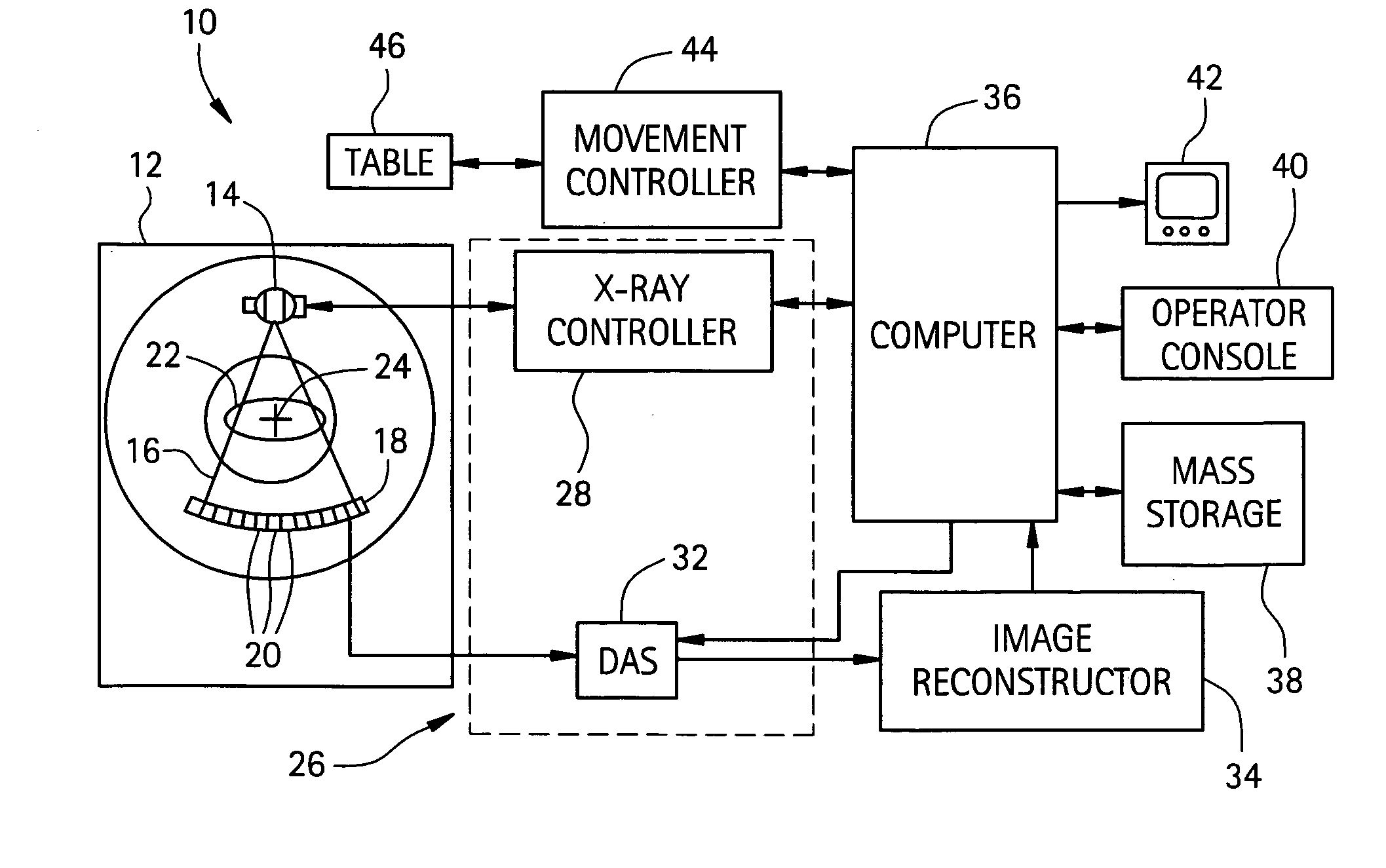
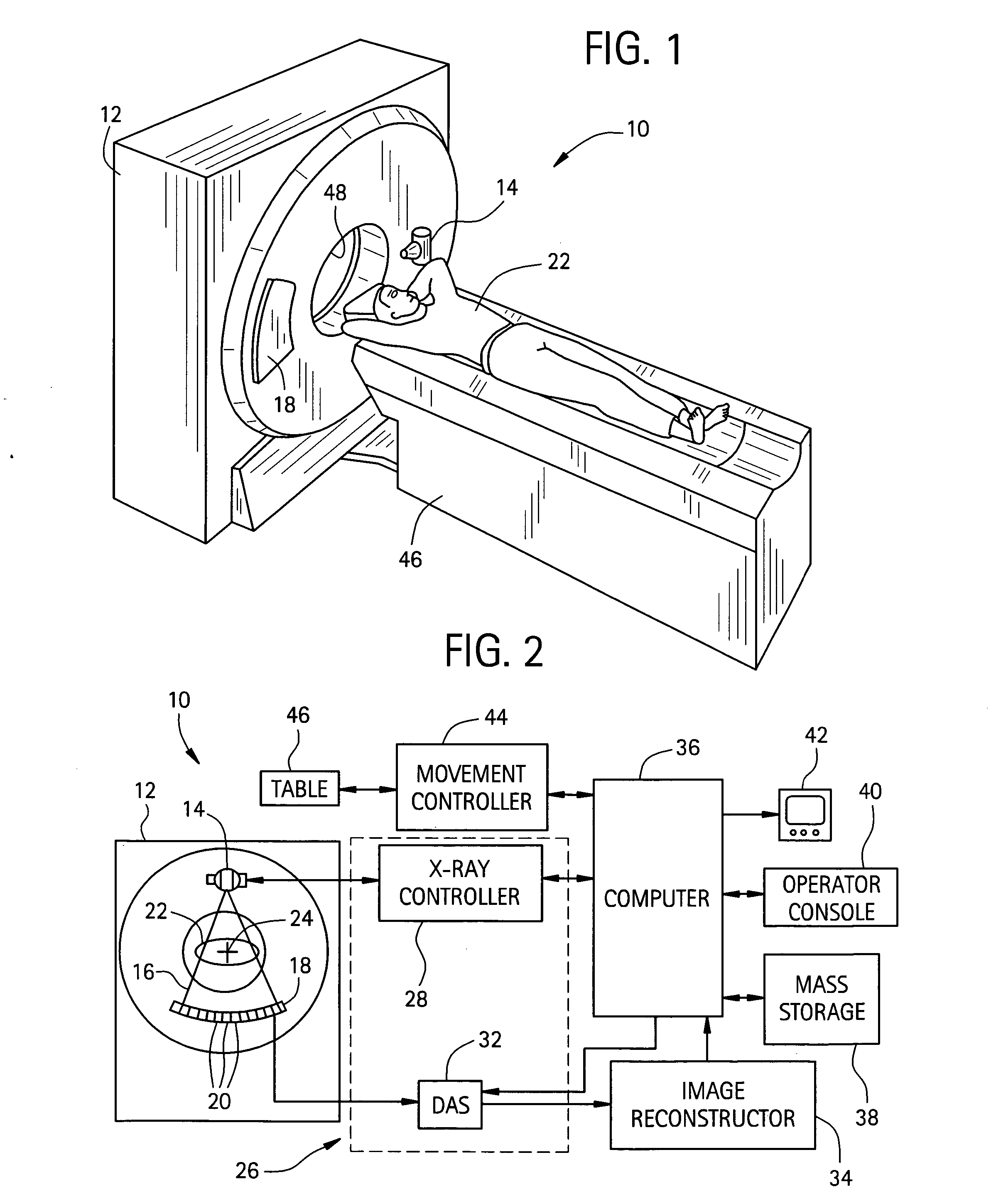
Certain embodiments of the present invention provide a system and method for correcting errors in detector cells, DAS channels, and / or DAS ASICs. Certain embodiments examine or “ride through” single cells and / or ASICs with a correction scheme. A DAS ASIC may be mapped to detector cells or channels to optimize opportunities for correction. Malfunctioning channels and / or ASICs may then be identified and correction applied.

For the purpose of illustration only, the following detailed description references a certain embodiment of a computed tomography (CT) imaging system. It is understood that the present invention may be used with other imaging systems (such as planar x-rays, ultrasound, magnetic resonance (MR), positron emission tomography (PET), single photon emission computed tomography (SPECT), micro computed tomography, and electron beam computed tomography (EBCT), and other imaging systems).

FIG. 1 illustrates a CT imaging system 100 in accordance with an embodiment of the pre...


PUM


Abstract

A method and system for an improved data acquisition system with an image detector array and an image processing system which finds a malfunctioning cell, interpolates a signal for the malfunctioning cell using neighboring channels of the cell, and corrects the interpolation with an error rate found in performing interpolations on neighboring rows with cells which are not malfunctioning. The image processing system may include a DAS and a reconstruction system. The step of finding a malfunctioning cell may be accomplished through a variety of methods, such as measuring discrepancies between a cell's and its neighboring cell's average readings over time and exposing the cells to x-rays which should produce similar readings in all the cells and comparing the cells' signals, looking for discrepancies. The step of interpolating and the step of correcting may take into consideration cells within the same projection view as the malfunctioning cell.

Description

RELATED APPLICATIONS [Not Applicable]FEDERALLY SPONSORED RESEARCH OR DEVELOPMENT [Not Applicable]MICROFICHE / COPYRIGHT REFERENCE [Not Applicable]BACKGROUND OF THE INVENTION The present invention relates to imaging systems and the accuracy of the image displayed to the user. More specifically, the invention relates to dynamically predicting signals of malfunctioning cells or suspected malfunctioning cells in an array of sensing devices, by utilizing other known signals. Medical diagnostic imaging systems encompass a variety of imaging modalities, such as planar x-rays, ultrasound, magnetic resonance (MR), electron beam tomography (EBT), positron emission tomography (PET), single photon emission computed tomography (SPECT), micro computed tomography, and macro computed tomography imaging systems, and the like. Medical diagnostic imaging systems generate images of an object, such as a patient, through exposure to an energy source, such as x-rays passing through a patient. A generat...

Claims


Application Information

Patent Timeline
IPC IPC(8): A61B6/03H04N5/32H05G1/64
CPCA61B6/032A61B6/585H04N5/3675H04N5/32A61B6/586H04N25/683
Inventor HSIEH, JIANGWILLIAMS, EUGENE CLIFFORD
Owner GENERAL ELECTRIC CO
Why Eureka
Try Eureka