
Plastic co-extrusion apparatus with selectable polymer flow control and product produced using the apparatus

a technology of coextrusion apparatus and selectable polymer, which is applied in the direction of dough shaping, manufacturing tools, applications, etc., can solve the problems of difficult to insert the selector pin in the wrong way, and achieve the effect of improving the uniformity of the film, simple and inexpensive, and high uniformity

Active Publication Date: 2005-03-24
DAVIS STANDARD
View PDF7 Cites 6 Cited by
  • Summary
  • Abstract
  • Description
  • Claims
  • Application Information

AI Technical Summary

Benefits of technology

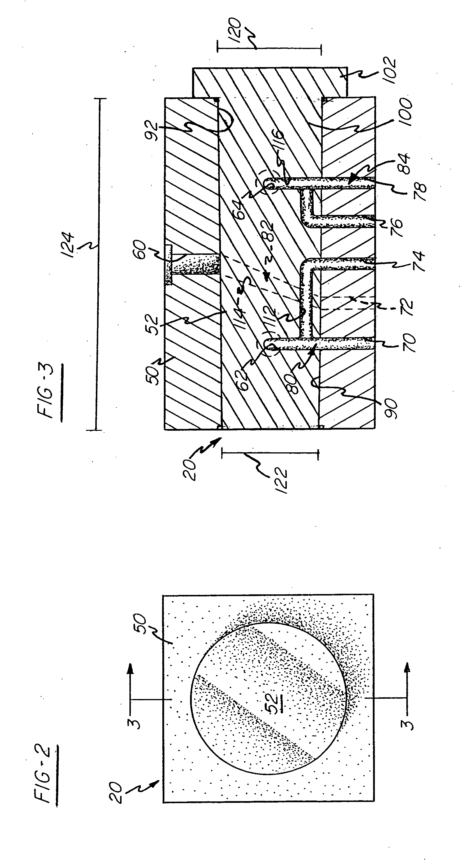
[0009] The inward taper of the preferred selector pin and socket permits the easy removal of the selector pin from the socket. Since the selector pin is tapered, a small outward movement of the selector pin relative to the socket tends to release the engagement between the two elements. This allows the selector pin to be removed without significant galling or other mechanical damage, even when the clearance between the selector pin and the socket is sufficiently tight to form a metal-to-metal mechanical seal. Furthermore, since the selector pin and socket are tapered, it is difficult to insert the selector pin in the wrong way.
[0018] The preferred structure provides significant flexibility in the arrangement of the lanes within a layer. The arrangement of the lanes need not be symmetrical about a centerline of the sheet.

Problems solved by technology

Furthermore, since the selector pin and socket are tapered, it is difficult to insert the selector pin in the wrong way.

Method used


Image

  • Plastic co-extrusion apparatus with selectable polymer flow control and product produced using the apparatus
  • Plastic co-extrusion apparatus with selectable polymer flow control and product produced using the apparatus
  • Plastic co-extrusion apparatus with selectable polymer flow control and product produced using the apparatus

Examples


Embodiment Construction

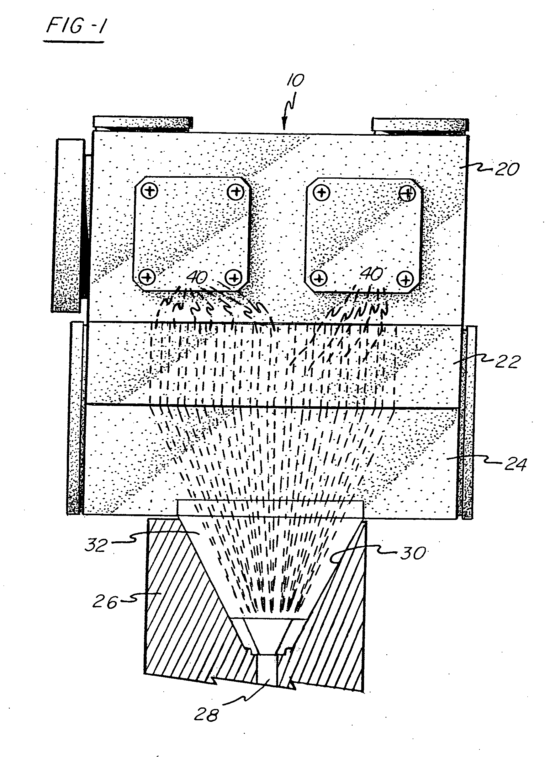
[0032] Referring to FIG. 1, preferred co-extrusion apparatus 10 comprises a plug-type flow diverter or layer sequencer 20; an intermediate height adjustment block 22; a transitional aspect ratio block 24; and an extruder die 26 defining an outlet 28 and a recess 30 communicating with the outlet 28. Most preferably, a demountable flow velocity profiler cartridge or combining block 32 is positioned in the recess 30. In use, resin or fluent polymer from a plurality of extruders (not shown) enters the layer sequencer 20. The resin or fluent polymer is directed through the layer sequencer 20 so as to form a sequence of polymer flows along paths 40. (Although provision for fourteen polymer flows is suggested in FIG. 1, the number of such flows is not critical to the invention.) These polymer flow paths 40 extend through the intermediate height adjustment block 22 and converge toward one another in the transitional aspect ratio block 24. The polymer flow paths 40 further converge and narro...


PUM

PropertyMeasurementUnit
temperaturesaaaaaaaaaa
aspect ratioaaaaaaaaaa
transitional aspect ratioaaaaaaaaaa

Abstract

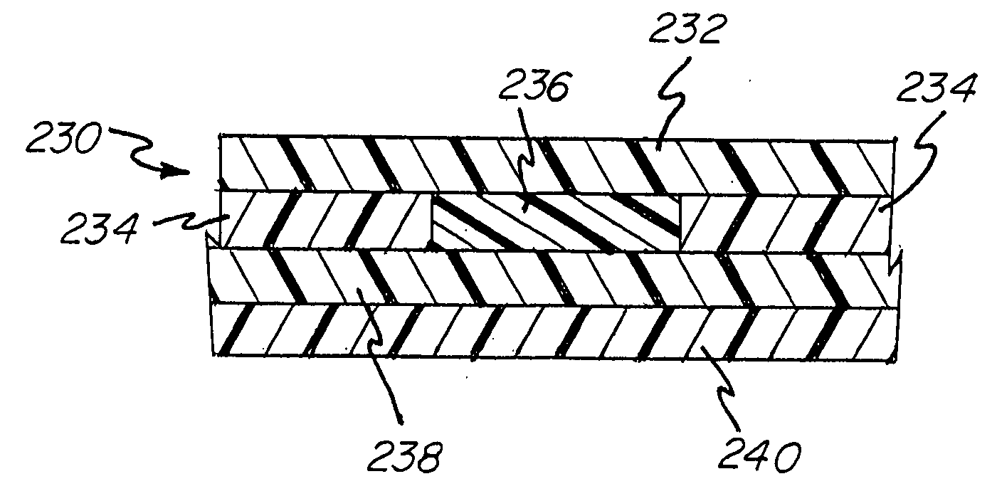
Co-extrusion apparatus for manufacturing a laminated plastic film or sheet comprises a plug-type layer sequencer including a plurality of channels for conducting a plurality of polymer flows; a transitional aspect ratio block for inducing the plurality of polymer flows to converge; and a flow velocity profiler cartridge for combining the plurality of polymer flows to form the film. In accordance with one embodiment, the layer sequencer includes a tapered selector pin which minimizes mechanical damage when the selector pin is removed. In accordance with another embodiment, the flow velocity profiler cartridge includes inserts fitting within cavities for controlling the polymer flows which form the layers of the film or sheet manufactured by the apparatus. At least one such insert defines lanes within an associated cavity so as to promote the formation of lanes of differing polymer composition within at least one layer of the laminated sheet or film.

Description

CROSS-REFERENCE TO RELATED APPLICATIONS [0001] This application is a continuation of International Application No. PCT / US03 / 05123 having an international filing date of Feb. 20, 2003, which designated the United States, and which in turn claims the benefit under 35 USC § 119(e) of U.S. Provisional Patent Application Ser. No. 60 / 358,974, filed Feb. 22, 2002, the entireties of which are incorporated herein by reference.BACKGROUND OF THE INVENTION [0002] This invention relates to the field of apparatus for co-extruding laminated polymer films or sheets, and more particularly to co-extrusion apparatus adapted to selectively deliver polymer from a plurality of extruders to reconfigurable, substantially parallel, converging channels so as to form laminated plastic films or sheets. [0003] Plug-type flow diverters or layer sequencers have been employed in the co-extrusion of laminated plastic films and sheets. Known plug-type layer sequencers, such as those taught in Cloeren U.S. Pat. No. 4...

Claims


Application Information

Patent Timeline
Patent Type & Authority Applications(United States)
IPC IPC(8): B29C48/255B29C48/08B29C48/21B29C48/305B29C48/49B29C48/50B32B3/00B32B7/02
CPCB29C47/0021B29C47/062B29C47/065B29C47/14B29C47/145B29C47/56Y10T428/24132B29K2105/0032B29K2995/0092B32B3/00B32B7/02Y10T428/24942B29C47/705B29C48/08B29C48/19B29C48/21B29C48/305B29C48/307B29C48/49B29C48/705Y10T428/31935B29C48/255B32B2307/402B32B27/308B32B27/08
Inventor WATSON, TIMOTHY P.CHRISTIE, ANDREW W.
Owner DAVIS STANDARD
Learn More