Electric field spraying of surgically implantable components

a technology of surgical implants and spray coating, applied in the direction of prosthesis, packaging goods, foodstuffs, etc., can solve the problems of thrombosis or restnosis, interfere with the mechanical performance of the stent, and the pneumatic spray coating method is somewhat inefficien

Inactive Publication Date: 2005-03-24
BATTELLE MEMORIAL INST
View PDF16 Cites 18 Cited by
  • Summary
  • Abstract
  • Description
  • Claims
  • Application Information

AI Technical Summary

Problems solved by technology

However, stents may still stimulate foreign body reactions that result in thrombosis or restenosis.
Dip coating using high viscosity solutions typically causes bridging, i.e., forming of a film across the open space between structural members of the device.
This bridging can interfere with the mechanical performance of the stent, such as expansion during deployment in a vessel lumen.
However, the quality and quantity of the material deposited on the implantable component are critical and pneumatic spraying methods require especially close control of process parameters such as fluid viscosity, spray nozzle condition, material deposition rates, and target placement relative to the spray nozzle to name a few.
Pneumatic spray coating methods can be somewhat inefficient.
For example, material lost due to overspray (a function of target component geometry and nozzle placement) and requirements for continuous nozzle maintenance and high solvent concentrations (to prevent clogging and process downtime) are key issues of concern.
Particles are lost due to the atomization process and this loss also results in the loss of significant amounts of the pharmaceutical agent(s), which can be quite costly.
Thus, it can be difficult to achieve an adequate and uniform coating over the entire surface of the device since the outer surface effectively shields the inner surface from the effects of the electrostatic charge.

Method used


Image

  • Electric field spraying of surgically implantable components
  • Electric field spraying of surgically implantable components
  • Electric field spraying of surgically implantable components

Examples


Embodiment Construction

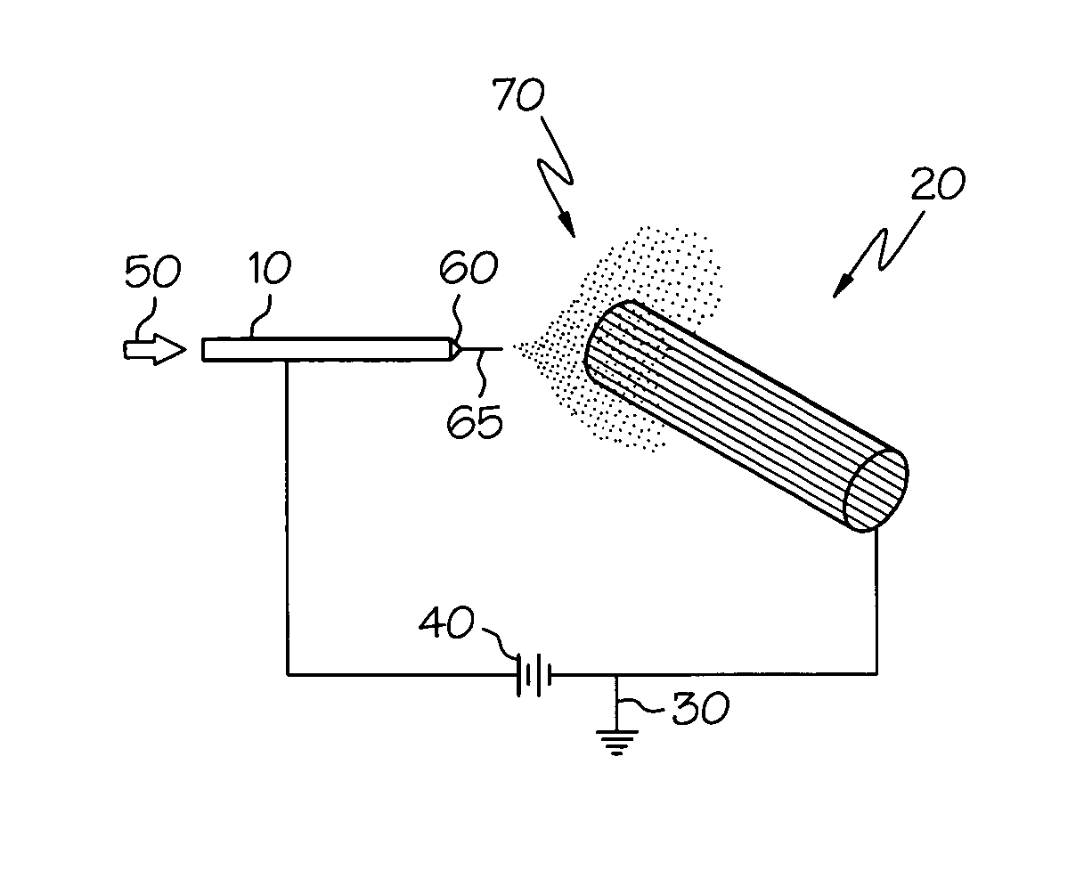
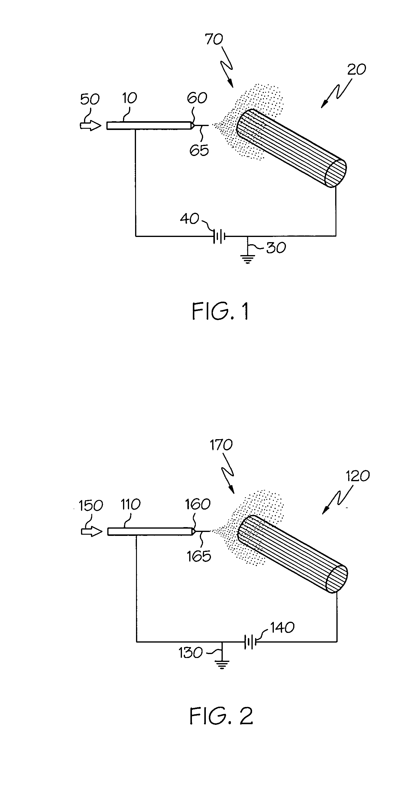
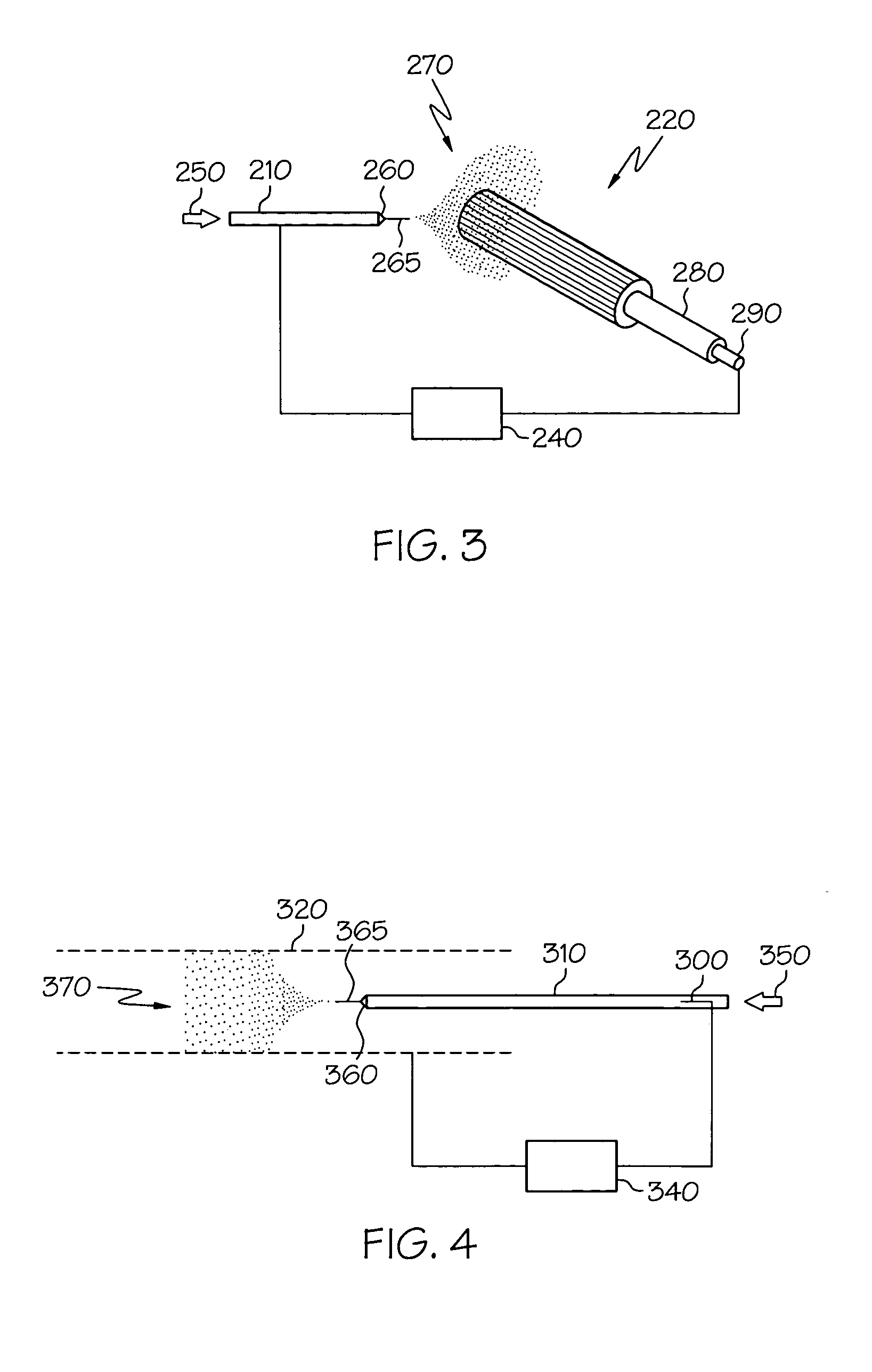
[0024] Significant improvements to the process of stent (medical component) coating can be realized by delivering the coating material via electric field spraying, specifically electrohydrodynamic (“EHD”) droplet generation, whereby the formulation is delivered to a spray site where it is exposed to an electric field and forms a so-called cone-jet configuration to produce highly-charged, micron-sized droplets having nearly uniform size. The term “EHD spray” as used herein refers to a freely divided spray of liquid droplets generated by applying an electric field to a liquid at a spray head or spray edge. In EHD spray technology, the potential of the electric field is sufficiently high to overcome the surface tension of the liquid. The cone shape of the liquid at a spray site results from the electric field and surface tension forces balancing each other. The so-called Taylor cone was mathematically described by Geoffrey Taylor; hence, the phenomenon bears his name. At the apex of th...


PUM

PropertyMeasurementUnit
diameteraaaaaaaaaa
diameteraaaaaaaaaa
diameteraaaaaaaaaa

Abstract

This invention relates to a method for depositing a coating onto an implantable medical component using electrohydrodynamics (“EHD”). The method utilizes EHD to comminute a suitable liquid which then form fibers or particles. The thus-formed fibers or particles are electrically attracted to the medical component and coat at least one surface of the medical component. A wide-variety of liquid formulations can be utilized to deliver a wide-variety of, for example, therapeutic substances, either alone of in combination. Fiber-based and particle-based coatings may be applied as well as combinations thereof. Also disclosed are medical components comprising such coatings, particularly stents.

Description

[0001] This application claims priority to U.S. pat. app. Ser. No. 60 / 504,816 filed Sep. 22, 2003, the contents of which is hereby incorporated as if fully rewritten herein.FIELD OF THE INVENTION [0002] The present invention provides a method of applying a coating to an implantable medical component either alone or in a combination with a therapeutic substance. More specifically, the present invention relates to electric field spray-coating of stents with therapeutic substances, wherein the stents are designed for storing and releasing the therapeutic substances, for instance, such as those used in the treatment of restenosis. BACKGROUND OF THE INVENTION [0003] When blood vessels are treated, stents are frequently used to prevent vessel blockage from restenosis. Stents are well-known in the medical arts. A stent is typically an open tubular structure that has a pattern (or patterns) of apertures extending from the outer surface of the stent to the lumen. The stent can have either so...

Claims


Application Information

Patent Timeline
Patent Type & Authority Applications(United States)
IPC IPC(8): A61F2/00A61L31/10B05D1/06
CPCA61F2250/0067A61L31/10B05D1/06B05D2258/00D01D5/0084C08L67/04Y10T428/249924
Inventor DVORSKY, JAMES E.SCOTT, K. BRYAN
Owner BATTELLE MEMORIAL INST
Why Eureka
Try Eureka