
Fuel cell bipolar separator plate

a technology of bipolar separator and fuel cell, which is applied in the field of bipolar separator plate, can solve the problems of affecting the control of fuel cell, presenting serious problems with respect to maintaining cell integrity, and close tolerance, and presenting very difficult engineering problems

Inactive Publication Date: 2005-03-24
GAS TECH INST
View PDF19 Cites 54 Cited by
  • Summary
  • Abstract
  • Description
  • Claims
  • Application Information

AI Technical Summary

Benefits of technology

[0010] Accordingly, it is one object of this invention to provide a fuel cell stack having a compact design such that the number of fuel cell units per inch of fuel cell stack height for a given electrical output is increased over conventional fuel cell stacks of a corresponding type.
[0012] It is another object of this invention to provide a fluid cooled bipolar separator plate for use in fuel cell stacks having enhanced conductivity properties.

Problems solved by technology

One issue associated with successful operation of each of these fuel cell types is the control of fuel cell temperature and the removal of products generated by the electrochemical reactions from within the fuel cell.
Cell stacks containing several hundred cells present serious problems with respect to maintaining cell integrity during heat-up and operation of the fuel cell stack.
Due to thermal gradients between the cell assembly and cell operating conditions, differential thermal expansions, and the necessary strength of materials required for the various components, close tolerances and very difficult engineering problems are presented.
In this regard, cell temperature control is highly significant and, if it is not accomplished with a minimum temperature gradient, uniform current density will not be maintainable, and degradation of the cell will occur.
The larger the fuel cell stack, the more difficult it becomes to maintain stack integrity and operation.

Method used


Image

  • Fuel cell bipolar separator plate
  • Fuel cell bipolar separator plate
  • Fuel cell bipolar separator plate

Examples


Embodiment Construction

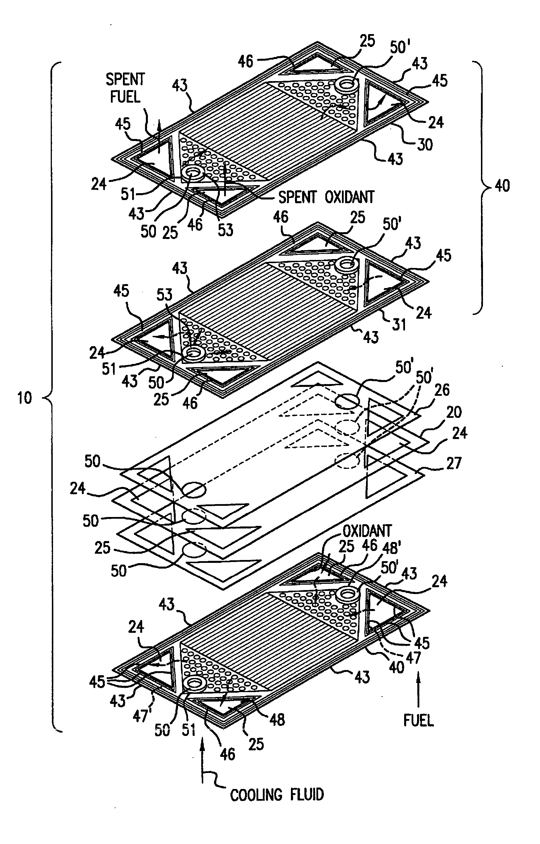
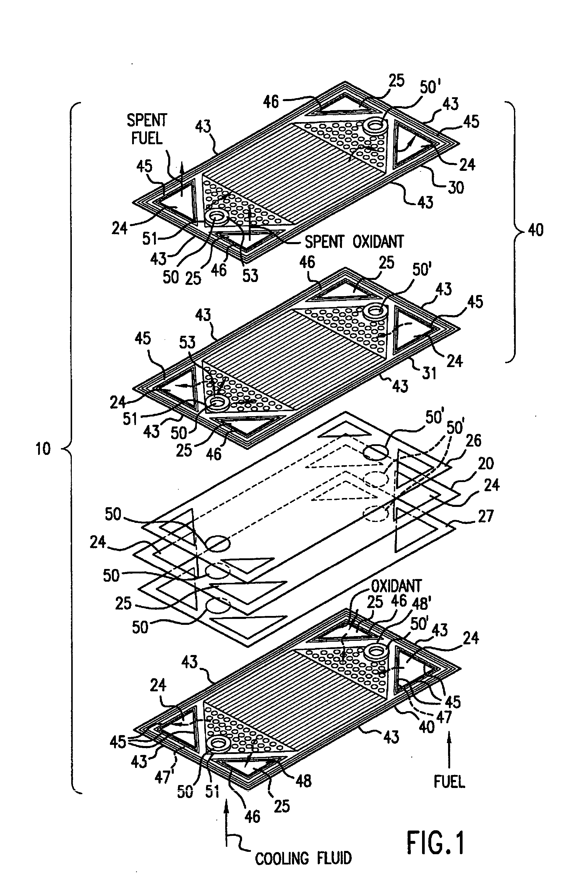
[0020]FIG. 1 is an exploded perspective view of a portion of a polymer electrolyte membrane fuel cell stack 10 in accordance with one embodiment of this invention. Although described herein in the context of a polymer electrolyte membrane fuel cell, as previously stated, this invention is suitable for use in other types of fuel cells, including molten carbonate, solid oxide and phosphoric acid, and such other types of fuel cells are deemed to be within the scope of this invention. Polymer electrolyte membrane fuel cell stack 10 comprises a plurality of polymer electrolyte membrane fuel cell units, each of which comprises a membrane-electrode-assembly (MEA) 20 comprising a thin, proton conductive, polymer membrane-electrolyte having an anode electrode film (anode) formed on one face thereof and a cathode electrode film (cathode) formed on the opposite face thereof, which membrane-electrode-assembly 20 is sandwiched between electrically conductive elements 26, 27 which serve as curren...


PUM

PropertyMeasurementUnit
power densityaaaaaaaaaa
areaaaaaaaaaaa

Abstract

A bipolar separator plate for a fuel cell stack constructed of at least two coextensive sheet metal elements shaped to promote the distribution of reactant gases to the electrodes of the fuel cell units of the fuel cell stack. The coextensive sheet metal elements are corrugated and fitted together to form at least one coolant flow channel between corresponding peaks, or valleys, of the corrugations of the sheet metal elements.

Description

BACKGROUND OF THE INVENTION [0001] 1. Field of the Invention [0002] This invention relates to a bipolar separator plate for use in fuel cell systems. More particularly, this invention relates to a fluid cooled, bipolar sheet metal separator plate for use in fuel cell stacks. This invention is applicable to all fuel cell types, including molten carbonate, solid oxide, phosphoric acid and polymer electrolyte membrane fuel cells. Although the concept of this invention may be applied to bipolar separator plates for a variety of fuel cell designs, it is particularly suitable for use in fuel cell stacks in which the fuel and oxidant are provided to each of the fuel cell units comprising the fuel cell stack through internal manifolds. [0003] 2. Description of Related Art [0004] There are a number of fuel cell systems currently in existence and / or under development which have been designed and are proposed for use in a variety of applications including power generation, automobiles, and oth...

Claims


Application Information

Patent Timeline
Patent Type & Authority Applications(United States)
IPC IPC(8): H01M8/02H01M8/04H01M8/08H01M8/10H01M8/12H01M8/24H02J
CPCH01M8/0206H01M8/021H01M8/0228H01M8/0247H01M8/0254Y02E60/50H01M8/0267H01M8/0297H01M8/1002H01M8/249H01M8/026H01M8/0258H01M8/241H01M8/1007H01M8/2483
Inventor MARIANOWSKI, LEONARD G.
Owner GAS TECH INST
Learn More