Connector coupling/decoupling tool

a technology for coupling/decoupling tools and connectors, which is applied in the direction of manufacturing tools, instruments, transportation and packaging, etc., can solve the problems of increasing the density of connector ports, increasing the size of electronic equipment, and increasing the volume of connectors

Inactive Publication Date: 2005-03-31
RICHCO
View PDF19 Cites 83 Cited by
  • Summary
  • Abstract
  • Description
  • Claims
  • Application Information

AI Technical Summary

Benefits of technology

[0004] The present invention provides a connector tool capable of holding a cable connector, for coupling and / or decoupling the connector into or from a connector port in an area having a high density of connector ports. The connector tool comprises a sleeve and a gripper, wherein the gripper has at least two fingers that form a slot for engaging the connector. The fingers are capable of being drawn into the sleeve to form a compartment in interlocking engagement with the connector. In an embodiment, the connector tool is capable of handling a SC fiber optic cable connector. In another embodiment, the connector tool is capable of handling an electrical cable connector.

Problems solved by technology

However, as electronic equipment becomes smaller, more components are being squeezed into tighter spaces.
Accordingly, cables that service the components are also becoming densely packed.
As more cables are attached to a piece of equipment, individual cable connectors have become more difficult to insert or extract from the equipment due to the corresponding increase in the density of cable connectors.
The tight space between cable connectors prevent fingers from adequately reaching a particular connector without disturbing, and possibly damaging, adjacent connectors.
Tugging at the cables is an unsatisfactory alternative to plugging or unplugging the cables by the connectors because the components within the cables can be damaged by rough handling.
Conversely, the cables are generally too flexible to serve as a adequate handle for inserting the cable connectors into the equipment.
Moreover, even if the cables are stiff enough to support the connector to insert the connector into its port, such an effort may also induce stress at the junction between the cable and the connector, once again damaging the components within the cable.

Method used


Image

  • Connector coupling/decoupling tool
  • Connector coupling/decoupling tool
  • Connector coupling/decoupling tool

Examples


Embodiment Construction

[0014] The invention is described by the following examples. It should be recognized that variations based on the inventive features disclosed herein are within the skill of the ordinary artisan, and that the scope of the invention should not be limited by the examples. To properly determine the scope of the invention, an interested party should consider the claims herein, and any equivalent thereof. In addition, all citations herein are incorporated by reference. In the context of this invention, substantially similar components are referenced by the same number in the different figures.

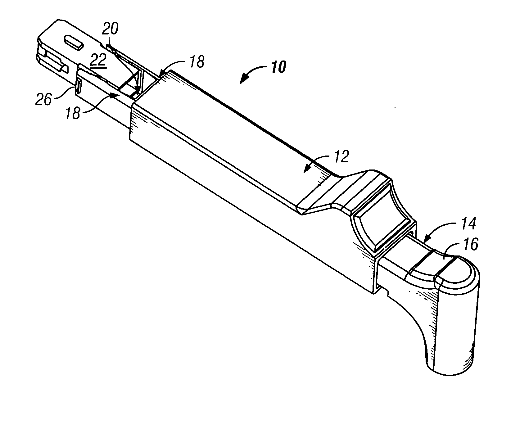
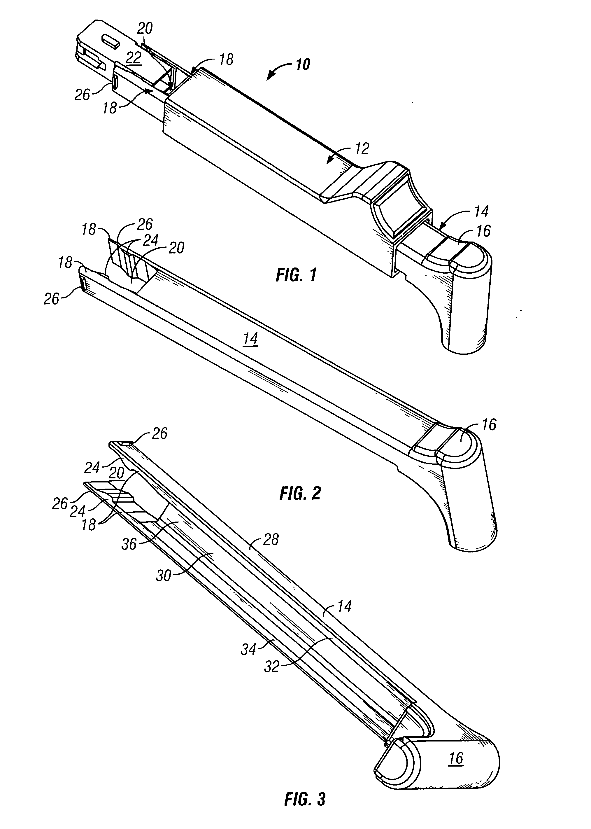
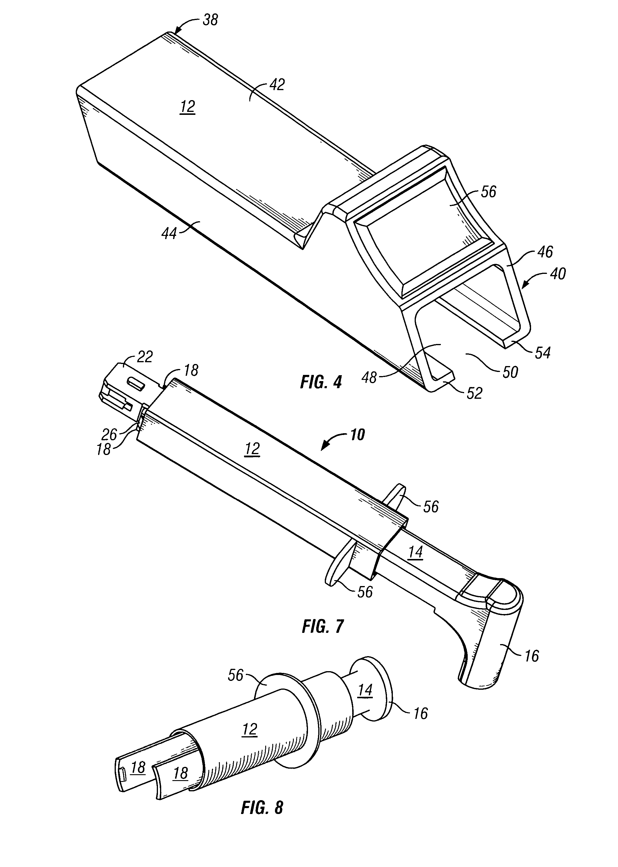
[0015] A connector coupling / decoupling tool 10 (hereinafter “connector tool”) according to the present invention comprises a sleeve 12 that is capable of sliding along an elongated gripper 14. Gripper 14 has a handle 16 at one end and fingers 18 at a distal end from handle 16. As shown in FIG. 1, fingers 18 form connector slot 20 spaced to engage connector 22. An embodiment of gripper 14 is shown g...


PUM

PropertyMeasurementUnit
densityaaaaaaaaaa
flexibleaaaaaaaaaa
stressaaaaaaaaaa

Abstract

The present invention provides a connector tool capable of holding a cable connector, for coupling and/or decoupling the connector into or from a connector port in an area having a high density of connector ports. The connector tool comprises a sleeve and a gripper, wherein the gripper has at least two fingers that form a slot for engaging the connector. The fingers are capable of being drawn into the sleeve to form a compartment in interlocking engagement with the connector. In an embodiment, the connector tool is capable of handling a SC fiber optic cable connector. In another embodiment, the connector tool is capable of handling an electrical cable connector.

Description

FIELD OF THE INVENTION [0001] The present invention provides a tool for coupling or decoupling a connector from a connection port. BACKGROUND [0002] Currently, a large number of electronic equipment are connected to electrical, optical or other forms of signal transmission cables by quick-connect / disconnect connectors of the plug and receptacle type. However, as electronic equipment becomes smaller, more components are being squeezed into tighter spaces. Accordingly, cables that service the components are also becoming densely packed. As more cables are attached to a piece of equipment, individual cable connectors have become more difficult to insert or extract from the equipment due to the corresponding increase in the density of cable connectors. The tight space between cable connectors prevent fingers from adequately reaching a particular connector without disturbing, and possibly damaging, adjacent connectors. [0003] Tugging at the cables is an unsatisfactory alternative to plug...

Claims


Application Information

Patent Timeline
Patent Type & Authority Applications(United States)
IPC IPC(8): G02B6/38H01R43/22
CPCG02B6/3807Y10T29/53274H01R43/22G02B6/3898
Inventor ZELLAK, DARREN JAMES
Owner RICHCO
Why Eureka
Try Eureka