Discharge apparatus, plasma processing method and solar cell

a technology of discharge apparatus and plasma, which is applied in the direction of gas-filled discharge tubes, sustainable manufacturing/processing, and final product manufacturing, etc., can solve the problems of inability to completely eliminate non-uniform distribution and difficulty in creating uniform plasma to cope with large-area substrates, and achieve the effect of improving productivity and further improving productivity

Inactive Publication Date: 2005-03-31
IHI CORP
View PDF9 Cites 25 Cited by
  • Summary
  • Abstract
  • Description
  • Claims
  • Application Information

AI Technical Summary

Benefits of technology

Accordingly, the present inventors carried out fundamental investigations on the plasma homogenization using the inductively coupled electrodes and developed several antenna structures that positively utilize the standing waves that caused the deterioration of uniformity in the prior art inductively coupled electrode system. Here, for instance, a U-shaped antenna was used, which had a power feeding portion at one end and a grounded portion at the other end. The distances from the turning portion to the feeding portion and the grounded portion were set to be a half wavelength of the high-frequency wave to establish the standing wave at predetermined position over the electrode (PCT / JP 00 / 06189). Moreover, the antenna having such structure is used to construct array antenna, which makes it possible to generate plasma more uniformly over the larger area.
Then, the configuration in which the substrate bodies are placed on both sides of array antenna is repeatedly provided in plurality in the vacuum chamber. This further improved the productivity.

Problems solved by technology

In short, it was found difficult to create uniform plasma to cope with the large-area substrates so long as the electrode structures of the prior art are employed.
However, these methods cannot completely eliminate the nonuniform distribution due to the influence of standing wave.

Method used


Image

  • Discharge apparatus, plasma processing method and solar cell
  • Discharge apparatus, plasma processing method and solar cell
  • Discharge apparatus, plasma processing method and solar cell

Examples


example

Next, examples are given below to explain this invention more concretely.

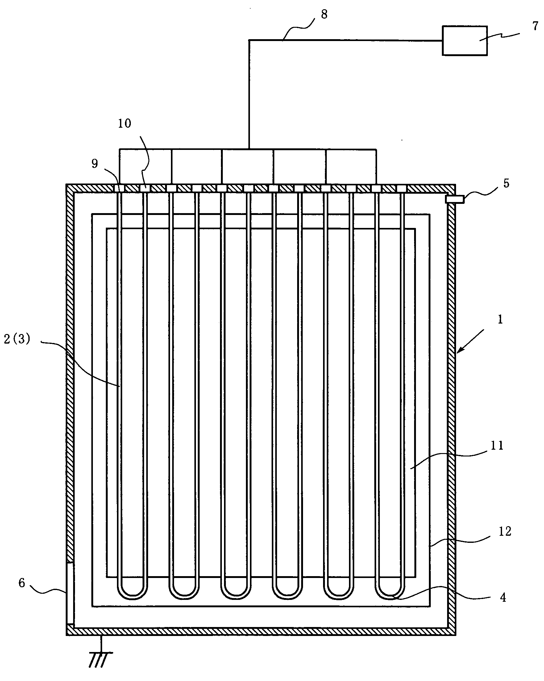
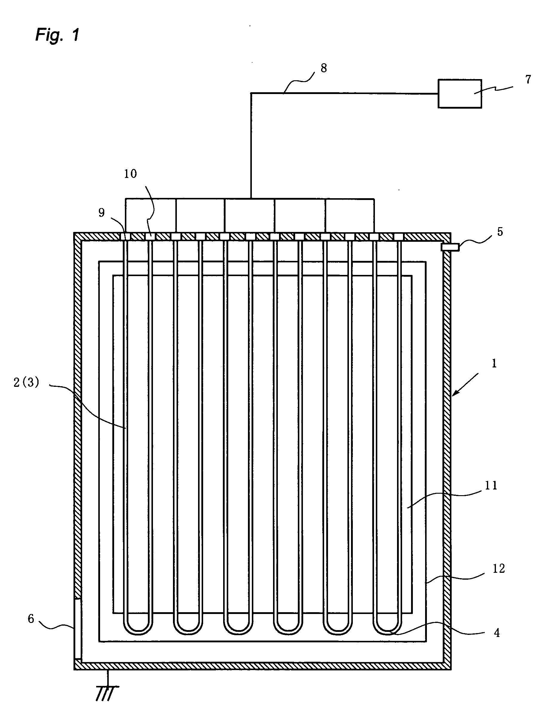
The following experiments were carried out using the plasma processing apparatus shown in FIG. 1. Using three types of antenna elements with the straight portion lengths of 0.5 m, 1.0 m, and 1.6 m, the measurement of reflected power and the visual observation of plasma density distribution were made at the conditions of excitation frequency of 50 MHz and discharge pressure of 10 Pa. In the case of the antenna with the length of 0.5 m, the discharge could not be induced. When the antenna with the length of 1.0 m was employed, the plasma was generated but the reflection was larger than 10% of the incident wave. The plasma was observed to have a distribution that the density was high around the center of straight portion and decreased towards the ends. In contrast, when the antenna with the length of 1.6 m was employed, the reflection power became very small, and the light and darkness of the plasma was hardly ...


PUM


Abstract

The object of this invention is to realize the new configuration of antenna and the electric power feeding method which substantially suppress the generation of standing wave and consequently to provide a discharge apparatus to generate plasma having an excellent uniformity, a plasma processing method for large-area substrate, and a solar cell manufactured with a high productivity. The present invention is composed of a plurality of U-shaped antenna elements having a power feeding end and a grounded end which are arranged to form an array antenna in such a way that the grounded end and the power feeding end are alternately placed in parallel at regular intervals on a plane, wherein the alternating current electric powers with the same excitation frequency are simultaneously fed to the power feeding ends with the phase shift of 180 degrees between adjacent power feeding ends, the excitation frequency of the alternating current power is 10 MHz-2 GHz, and the length of the conductor is set so that the measured ratio of reflected wave to incident wave is 0.1 or less at the power feeding end. It is also possible to determine the length La of straight conductor to hold the inequality: 0.5(1 / α)<La<10(1 / α). Here, α(1 / m) is a attenuation coefficient.

Description

FIELD OF THE INVENTION The present invention relates to a discharge apparatus, a plasma processing method, and a solar cell, and more particularly to the discharge apparatus to generate uniform plasma using an array antenna, the plasma processing method having an excellent productivity and uniformity, and the solar cell which can be manufactured with a high productivity. DESCRIPTION OF THE RELATED ART Solar cells have been noted and expected as a clean energy source, but their cost reduction is indispensable for their spread. It has, therefore, been earnestly desired to provide an apparatus to deposit high quality a-Si film with uniform thickness distribution over large-area substrate at a high throughput. In addition to the solar cells, there is a strong demand in various fields for uniform processing on a large-area substrate. For example, in manufacture of thin film transistors for driving a liquid crystal display, the production line for large-area substrates having one side o...

Claims


Application Information

Patent Timeline
Patent Type & Authority Applications(United States)
IPC IPC(8): H01J17/26H01J37/32H01J61/28H01L31/20H05H1/24
CPCH01J37/32091H01J2237/3132H01J2237/3137Y02E10/50H01L31/202H05H1/24H01J2237/3142H05H1/46Y02P70/50H05H1/463H01J37/32
Inventor UEDA, MASASHITAKAGI, TOMOKOITO, NORIKAZUWATABE, YOSHIMI
Owner IHI CORP
Why Eureka
Try Eureka