Thermal transfer image receiving sheet and image forming method using the same

Inactive Publication Date: 2005-03-31
KONICA MINOLTA PHOTO IMAGING
View PDF3 Cites 7 Cited by
  • Summary
  • Abstract
  • Description
  • Claims
  • Application Information

AI Technical Summary

Benefits of technology

An object of the present invention is to provide a thermal transfer image receiving sheet and an image forming method which enable to provide a superior antistatic properties, a superior conveyance property and an excellent handling property under generated electrostatic charge, without loosing a storage stability, an abrasion resistance and an adhesion property of the image.
According to one embodiment of the present invention, a thermal transfer image receiving sheet containing a support having an image receiving layer on one surface of the support and a backing layer on the other surface of the support is provided, the image forming method including, (i) forming an image via thermal transfer on the thermal tr

Problems solved by technology

Concerning the storage stability and permanence, however, the quality of an image formed by this method has not yet reached those of a silver salt picture.
When forming an image by a thermal sublimation transfer method, since the thermal transfer sheet and the thermal transfer image receiving sheet are put together and heated while conveyed through a printer, there may arise a problem that static electricity is generated resulting in a trouble in the conveyance or that dust is collected on the dye receiving layer surface of the thermal transfer image receiving sheet resulting in imperfect coloring.
While the protection layer described above is transferred by a thermal printer, there has often been a problem that a considerable amount of static electricity is generated when the protection layer is separated from the thermal transfer sheet, resulting in a trouble in the conveyance of a thermal transfer image receiving sheet and thermal transfer sheet in the thermal printer.
In addition, when multiple image prints are piled one over another after printing, the image receiving sheets adhere to each other due to static electricity, and therefore there sometimes arises a problem that multiple image prints cannot be piled up compactly, resulting in inconvenience in handling the prints.
With the above proposed methods, however, electrostatic charge of the thermal transfer image recei

Method used


Image

  • Thermal transfer image receiving sheet and image forming method using the same
  • Thermal transfer image receiving sheet and image forming method using the same
  • Thermal transfer image receiving sheet and image forming method using the same

Examples


example 1

<<Production of Thermal Transfer Image Receiving Sheet>>

[Production of Thermal Transfer Image Receiving Sheet 1]

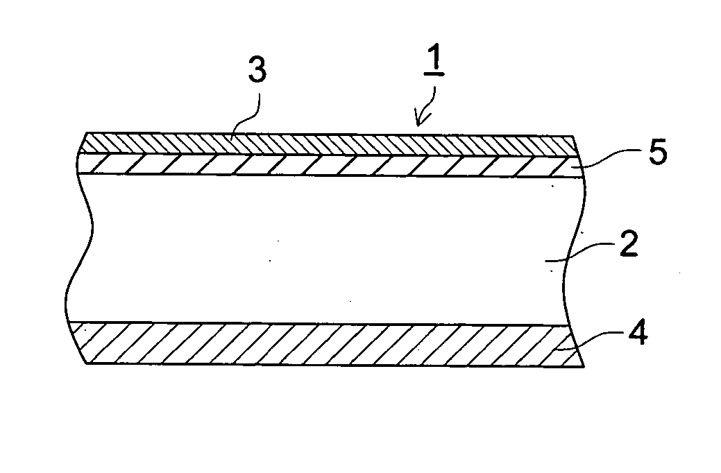
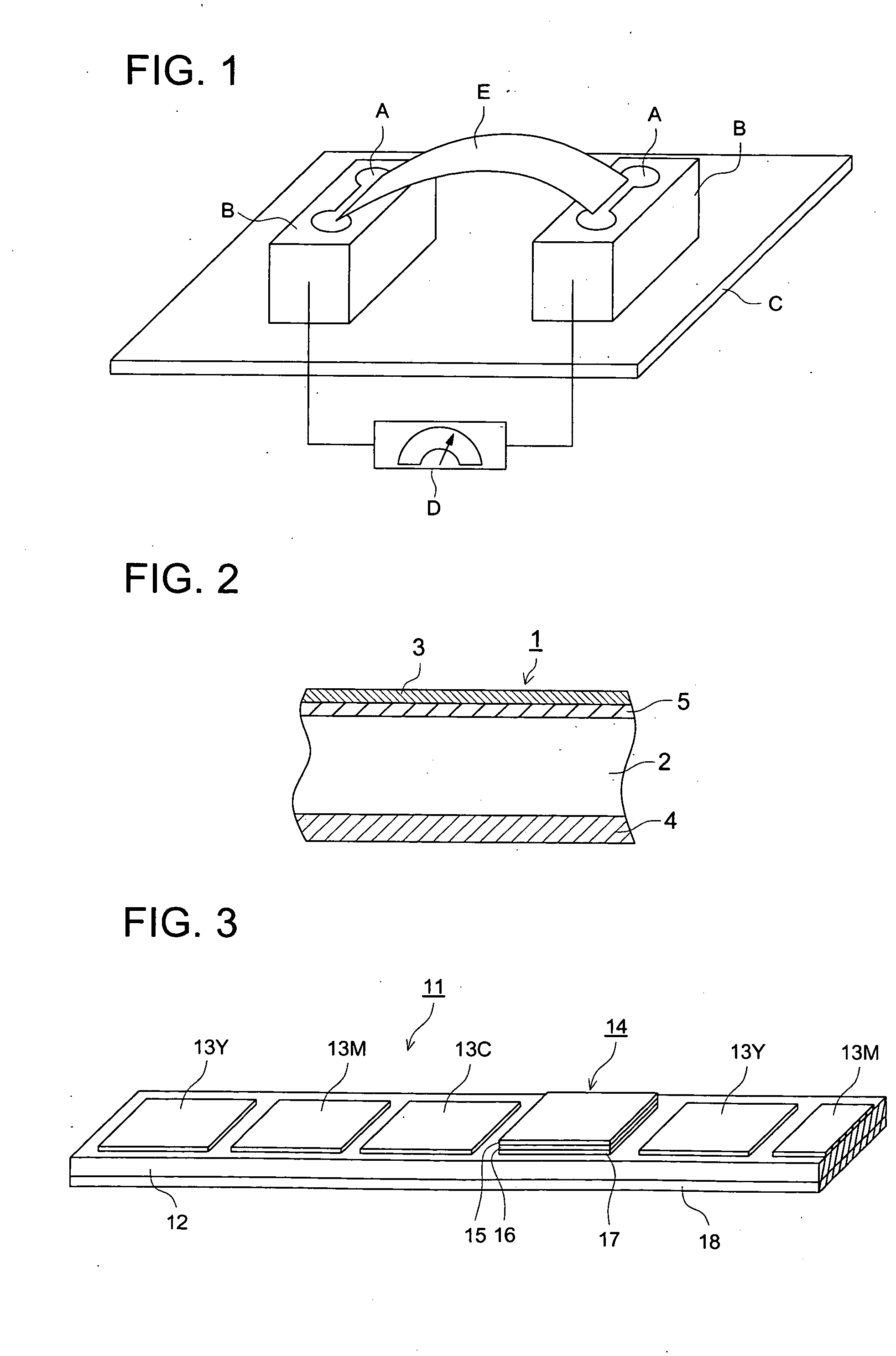
A corona discharge treatment was applied to one side of coat paper (basis weight 157 g / m2, OK Top Coat S manufactured by Oji Paper Co., Ltd.). Then, as backing resin layers, high-density polyethylene (hereinafter called HDPE) [Jeyrex LZ0139-2, density 0.952, manufactured by Nippon Polyolefin Co., Ltd.] blended with 15% by weight of ethylene-α-olefin copolymer [Tafiner A-4085 manufactured by Mitsui Chemical Co., Ltd.] and polypropylene (hereinafter called PP) [Jeyaromer LR711-5, density 0.905, manufactured by Nippon Polyolefin Co., Ltd.] were extruded into two layers by the well-known co-extrusion coating method using a multilayer T-die so that the HDPE layer side contacted the corona discharge treated surface of the coat paper. Extrusion quantity was adjusted so that the thickness of the backing resin layer became 14 μm for the ethylene-α-olefin copolymer blend...


PUM

PropertyMeasurementUnit
Percent by volumeaaaaaaaaaa
Sheet resistanceaaaaaaaaaa

Abstract

A thermal transfer image receiving sheet comprising a support having an image receiving layer on one surface of the support and a backing layer on the other surface of the support, wherein, (a) a first electrical resistance of the thermal transfer image receiving sheet is in a range of 1×10⁸-1×10¹² ohms per square before the transferable protection layer is transferred; and (b) a second electrical resistance of the thermal transfer image receiving sheet is in a range of 1×10⁸-1×10¹² ohms per square after the transferable protection layer is transferred and after the backing layer is removed, the first and second electrical resistances being measured by a salt bridge method.

Description

TECHNICAL FIELD The present invention relates to a thermal transfer image receiving sheet and to a method of forming an image in which an image is formed by using the thermal transfer image receiving sheet and a thermal transfer sheet at least containing a transferable protection layer, more precisely relates to a thermal transfer image receiving sheet and a method of forming an image in which an anti-scratching property and an excellent antistatic property are maintained even when the image is formed by a thermal transfer method, where a transferable protection layer is transferred. BACKGROUND A method of forming a color or monochrome image according to a known prior art is such that an ink sheet containing thermal diffusive dye, which has the property of being diffused and transferred by heat, is placed opposite to an image receiving layer of an image receiving sheet and the thermal diffusive dye is transferred onto the image receiving layer to form an image, using a thermal pri...

Claims


Application Information

Patent Timeline
IPC IPC(8): B41J2/335
CPCB41J2/33545B41J2/33515
Inventor KOYAMA, HIROKAZUWATANABE, HIROSHIYAMAGISHI, HIROAKINAKANE, HIROKI
Owner KONICA MINOLTA PHOTO IMAGING
Why Eureka
Try Eureka