Magnetic resonance imaging apparatus and magnetic resonance imaging method

a magnetic resonance imaging and magnetic resonance imaging technology, applied in the field of magnetic resonance imaging, can solve the problems of inability to stably image the region subject to measurement, inability to obtain information on the increase in temperature caused by heating, and inability to monitor temperature stably, so as to improve the accuracy and reliability of temperature measurement and improve image quality

Inactive Publication Date: 2005-03-31
HITACHI MEDICAL CORP
View PDF7 Cites 30 Cited by
  • Summary
  • Abstract
  • Description
  • Claims
  • Application Information

AI Technical Summary

Benefits of technology

[0018] With the above function, it is possible to improve the accuracy and the reliability in temperature measurement. Further, the temperature change of the portion subjected to measurement can be monitored by displaying the thus-determined temperature change distribution as a color image.
[0019] Further, as another example of the operation means for determining the necessary diagnosis information, there are an operation process for

Problems solved by technology

Therefore, it is difficult to stably image the region subjected to measurement.
In the latter case, the information of temperature increase caused by heating cannot be obtained.
The temperature sometimes increases and sometimes does not increase, or in some cases a heating region suddenly expands or disappears, whereby the temperature cannot be stably monitored.
Therefore, the result lacks reliability.
The above problem in measurement caused by movement of an examinee is a common problem when diagnosis is executed by measuring continuously and in time series the NMR signals from an imaging cross section including a region subjected to measurement and comparing the measured data of a plurality of imaging cross section obtained at different times, in addition to the measurement of the temperature distribution described above.
For example, MR angiography known as a blood vess

Method used


Image

  • Magnetic resonance imaging apparatus and magnetic resonance imaging method
  • Magnetic resonance imaging apparatus and magnetic resonance imaging method
  • Magnetic resonance imaging apparatus and magnetic resonance imaging method

Examples


Embodiment Construction

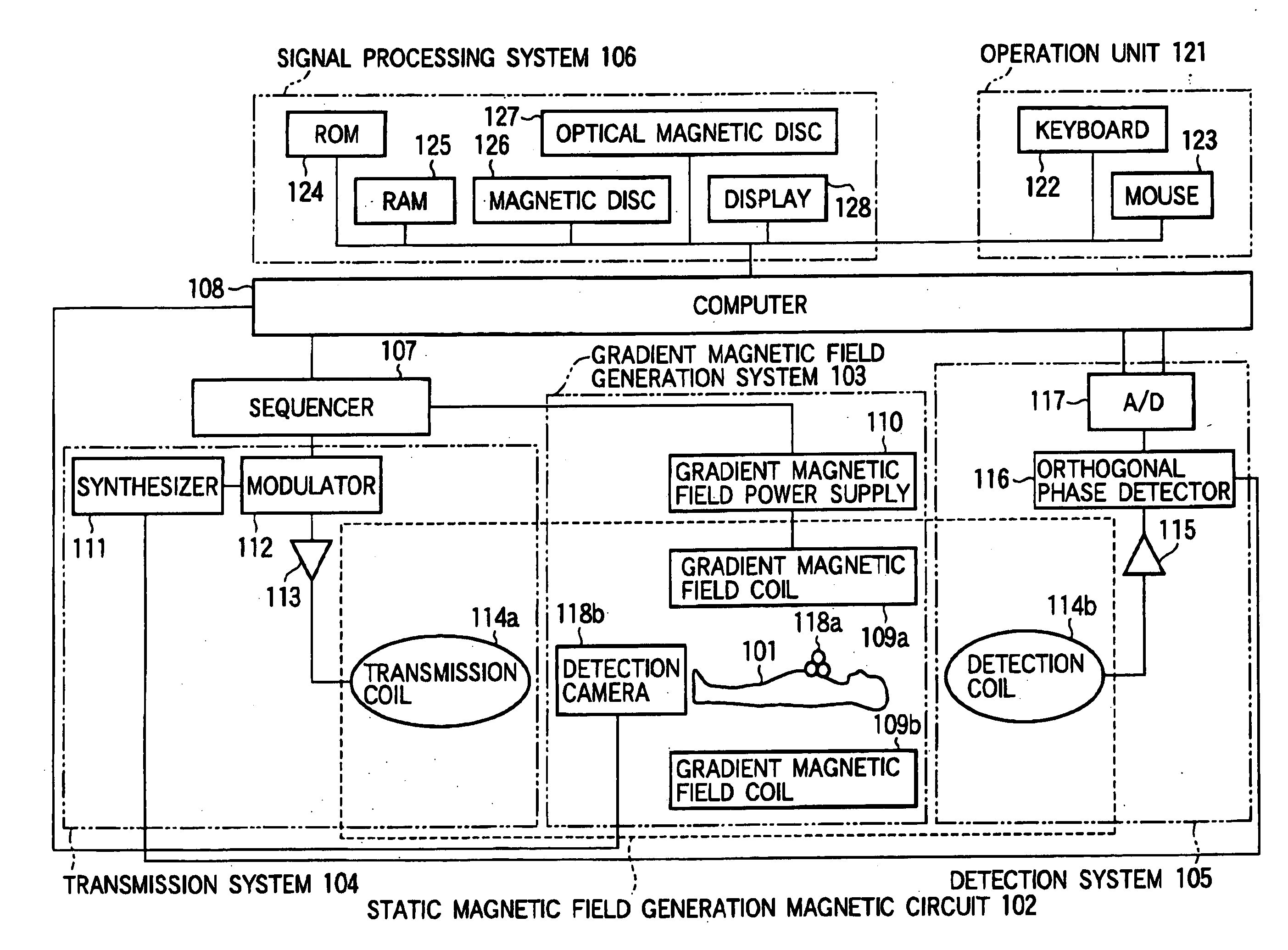
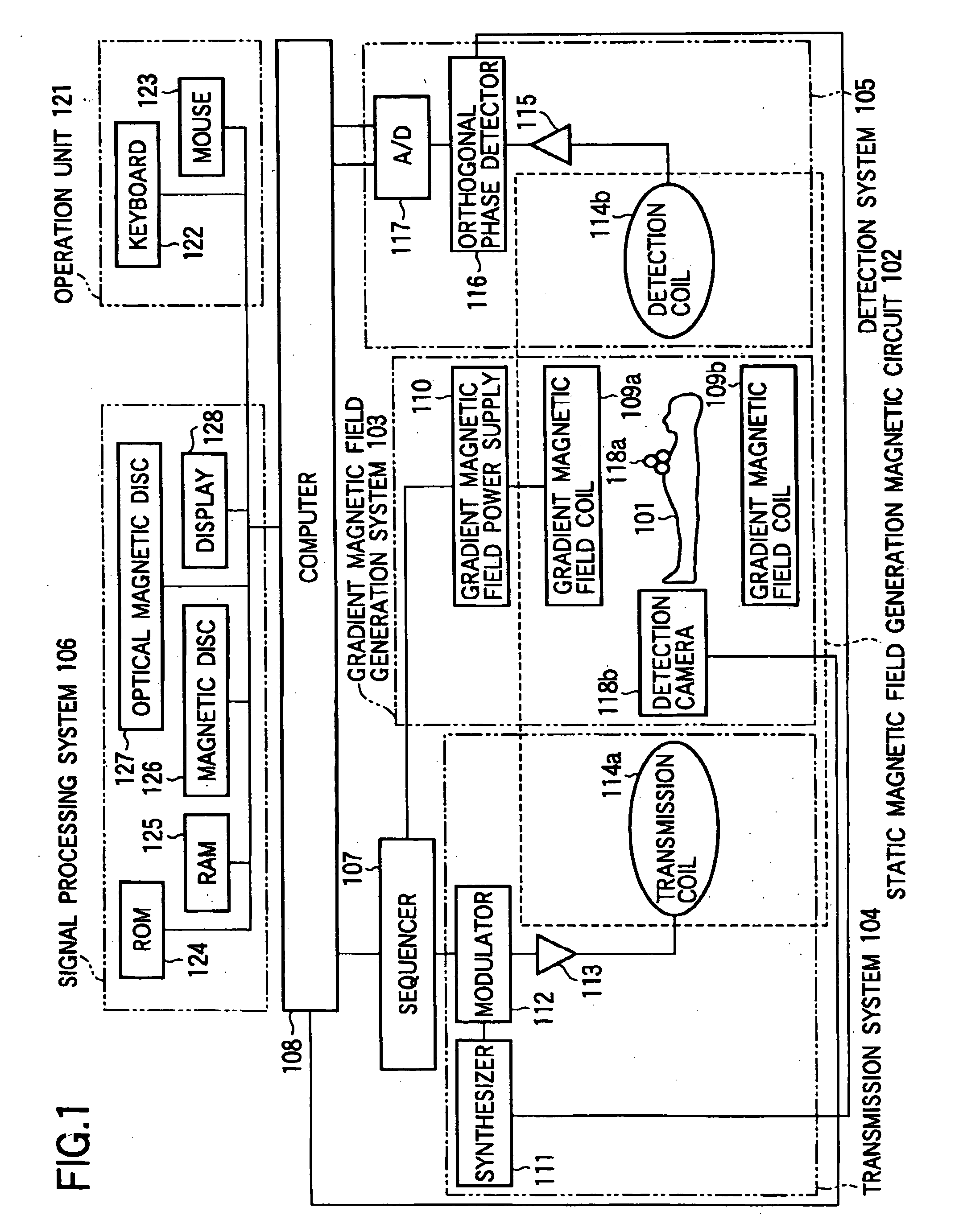
[0033] An embodiment of an MRI apparatus of the present invention will be described below with reference to the drawings. FIG. 1 is a view showing the overall arrangement of the MRI apparatus to which the present invention is applied. The MRI apparatus includes a static magnetic field generation magnetic circuit 102 composed of an electromagnet or a permanent magnet for generating a uniform static magnetic field H0 in an examinee 101, a gradient magnetic field generation system 103 for generating gradient magnetic fields Gx, Gy, Gz the intensities of which linearly change in three axis directions which are orthogonal to each other, a transmission system 104 for applying a radio-frequency magnetic filed (RF pulses) to the examinee 101, a detection system 105 for detecting NMR signals generated from the examinee 101, a gradient magnetic field generation system 103, a sequencer 107 for transmitting a command to the transmission system 104 and the detection system 105 and generating gra...


PUM


Abstract

A magnetic resonance imaging apparatus includes control means 107 and 108 for continuously performing magnetic resonance imaging of a cross section including a portion subjected to measurement of an examinee (101) at a predetermined time interval, operation means 108 for calculating diagnosis information related to the portion subjected to measurement by using a plurality of sets of nuclear magnetic resonance signals related to cross sections imaged at different time points by measuring nuclear magnetic resonance signals generated from the examinee 101, and a position detection device 118 having a detection camera 118b for detecting in non-contact manner the position (three-dimensional position and rotation angle around an orthogonal coordinate axis) of a pointer 118a provided outside the examines body and moving while interlocked with the biological movement of the examinee 101. The control means 108 sets the position of the cross section according to the position of the pointer 118a detected by the position detection device 118, thereby eliminating an affect of the biological movement and improving the accuracy and the reliability of the diagnosis information including differential processing of a portion subjected to measurement.

Description

TECHNICAL FIELD [0001] The present invention relates to a magnetic resonance imaging (hereinafter, referred to as MRI) apparatus and a magnetic resonance imaging method. Specifically, the present invention relates to setting a slice of the magnetic resonance imaging that is suitable for performing the continuously imaging of a portion subjected to measurement of an examinee which is moved by biological movement such as breath movement. BACKGROUND ART [0002] An MRI apparatus excites particular atomic nuclei (for example, protons) constituting an examinee by applying radio-frequency magnetic field pulse (hereinafter, referred to as an RF pulse) together with a gradient magnetic field for setting the slice to the examinee placed In a static magnetic field. The MRI apparatus reconstructs a tomogram inside the examinee based on a nuclear magnetic resonance (NMR) signals generated by the excitation to provide the tomogram with the diagnosis The MRI apparatus is used to set a slice includi...

Claims


Application Information

Patent Timeline
IPC IPC(8): A61B5/055A61B5/11G01R33/28G01R33/48
CPCA61B5/055G01R33/4804G01R33/28A61B5/11A61B5/70
Inventor KOMURA, KAZUMITAKAHASHI, TETSUHIKONAGAO, HISAKO
Owner HITACHI MEDICAL CORP
Why Eureka
Try Eureka