Intramedullary implant for fracture fixation

a technology of intramedullary implants and fractures, which is applied in the field of intramedullary implants for fracture fixation, can solve the problems of high deformation load across the fractured articular surface, loss of reduction of joint surface, and malposition of wrist, and achieves the effects of reducing the risk of failure, and maintaining the length of fragments

Inactive Publication Date: 2005-03-31
MEDOFF ROBERT J +2
View PDF4 Cites 80 Cited by
  • Summary
  • Abstract
  • Description
  • Claims
  • Application Information

AI Technical Summary

Benefits of technology

[0014] An object of the present invention is to provide an implant adapted to overcome the limitations noted above by placing a large surface area of contact at the tip of a buttressing element against an apical corner of a subarticular fragment, such as the radial styloid. The tip of the buttressing element of the implant is configured with a blunt shape to supports the

Problems solved by technology

If the radial styloid is not held out to length, the bones of the carpus (wrist) will subside proximally and result in high deforming loads across the fractured articular surface.
This can lead to loss of reduction of the joint surface and malposition of the wrist.
In addition, since the adjacent ulna is of normal length and the radius becomes short, significant dysfunction can occur to the adjacent radioulnar joint.
Finally, translation of the radial styloid to the radial side causes the end of the articular surface to spread apart, resulting in incongruity of the articular surface and a poor clinical result.
Current implants do not adequately address this problem of maintaining length to the radial styloid.
In addition, since the pins that cross the radial styloid are thin, the fragment can slide along the pins and lose length.
Standard buttress fixation plates placed either dorsally or volarly also do not adequately address this problem.
These also require exposure of the entire surface of the bone, which can be detrimental because of stripping of the blood supply and irritation of the soft tissues.
This type of approach requires a bulky plate to be placed on the superficial surface of the distal fragment in a region where many tendons and ligaments are in close apposition to the bone; this can result in tendon irritation and even rupture.
In addition, because these plates are placed on the dorsal

Method used


Image

  • Intramedullary implant for fracture fixation
  • Intramedullary implant for fracture fixation
  • Intramedullary implant for fracture fixation

Examples


Embodiment Construction

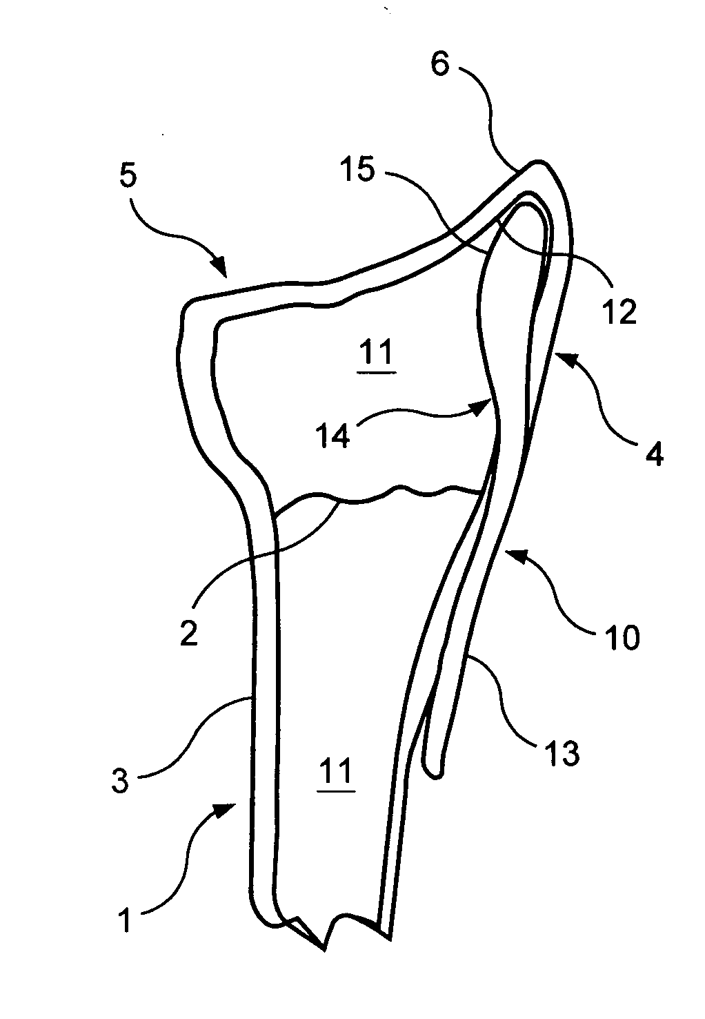
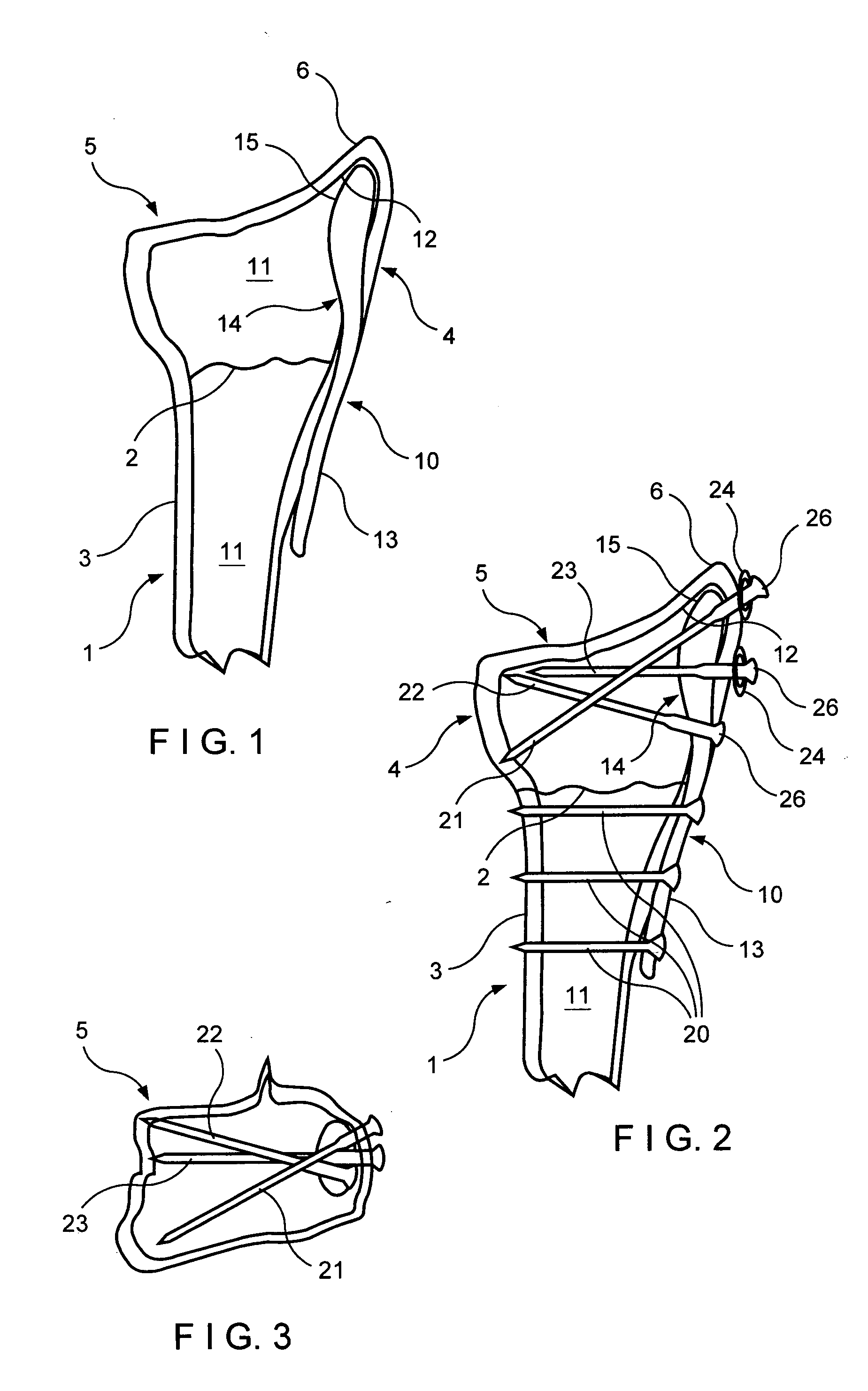
[0037] The invention will be described hereafter with reference to fixation of a fracture of the radius of the wrist utilizing an intramedullary implant which is braced against the apex of the lower tip of the radial styloid to serve as a prop or buttressing means to hold an unstable fragment of the fracture at length to prevent shortening. However, as will be evident to those skilled in the art, the invention is applicable to other fractures as well, in which the implant can be inserted into an intramedullary canal and braced in an inner apical surface of a bone fragment adjoining the fracture. Suitable examples are the distal end of the fibula, the medial malleolus of the ankle and the distal end of the ulna.

[0038] Referring to FIG. 1, therein is seen a bone 1, namely the radius of the wrist, in which a fracture 2 is present at its distal end and forms a stable proximal bone fragment 3 and an unstable distal bone fragment 4. The distal bone fragment 4 has a distal end 5 which inc...


PUM


Abstract

An implant for fracture fixation having external portion shaped to be externally engaged on and secured to a stable bone fragment on one side of a bone fracture and an integral internal portion sized and shaped for being inserted into and accommodated in an intramedullary canal of an unstable bone fragment on an opposite side of the fracture. The internal portion has an end with a rounded tip of bullet-shape for fitting in an apical space at an endosteal surface of the unstable bone fragment to provide a bearing support for the unstable bone fragment over a large area.

Description

FIELD OF THE INVENTION [0001] The invention relates to fracture fixation devices and particularly to devices for fixation of distal fractures of the radius. [0002] In particular, the invention relates to an intramedullary implant for such fracture fixation in which the implant includes a first portion adapted to be secured externally on stable bone and a second portion which enters into the intramedullary canal of the unstable bone fragment to be set and wherein the tip end of the second portion is shaped to fit in a space in an endosteal surface of the unstable bone fragment and suspend the unstable bone fragment by said tip end to prevent axial collapse or shortening of the unstable bone fragment. [0003] In the case of the fracture of the distal radius, the invention provides that the tip end of the intramedullary implant engage the subchondral bone of the radial styloid to maintain its length and position. [0004] The invention further relates to a method for fracture fixation wit...

Claims


Application Information

Patent Timeline
IPC IPC(8): A61B17/17A61B17/72A61B17/80A61B17/86
CPCA61B17/1721A61B17/1725A61B17/1728A61B2017/1782A61B17/8061A61B17/8695A61B17/72A61B17/1782
Inventor MEDOFF, ROBERT J.
Owner MEDOFF ROBERT J
Why Eureka
Try Eureka