Exhaust gas purification apparatus for internal combustion engine and method thereof

a technology of exhaust gas purification apparatus and internal combustion engine, which is applied in the direction of exhaust treatment electric control, electrical control, separation process, etc., to achieve the effect of effective purification

Inactive Publication Date: 2005-04-07
NISSAN MOTOR CO LTD
View PDF10 Cites 57 Cited by
  • Summary
  • Abstract
  • Description
  • Claims
  • Application Information

AI Technical Summary

Benefits of technology

[0005] The present invention, from the foregoing problem, has an object of providing an exhaust gas purification apparatus for an internal combustion engine and a method thereof, capable of effectively purifying also NOx at the filter regeneration.

Problems solved by technology

However, in a system where a total amount of the exhaust gas flows in the filter all the time, when the regeneration is carried out only in oxygen atmosphere, HC, CO are purified, but NOx is not purified.

Method used


Image

  • Exhaust gas purification apparatus for internal combustion engine and method thereof
  • Exhaust gas purification apparatus for internal combustion engine and method thereof
  • Exhaust gas purification apparatus for internal combustion engine and method thereof

Examples


first embodiment

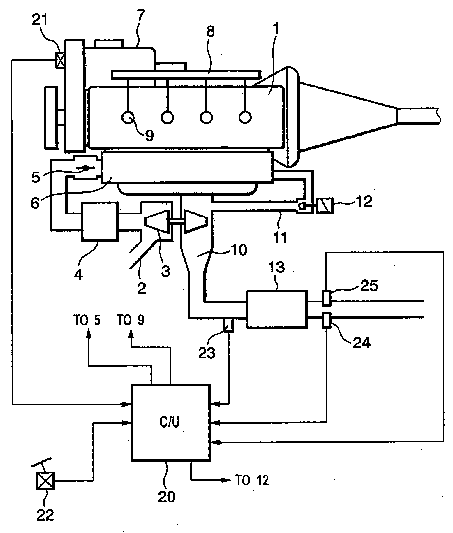
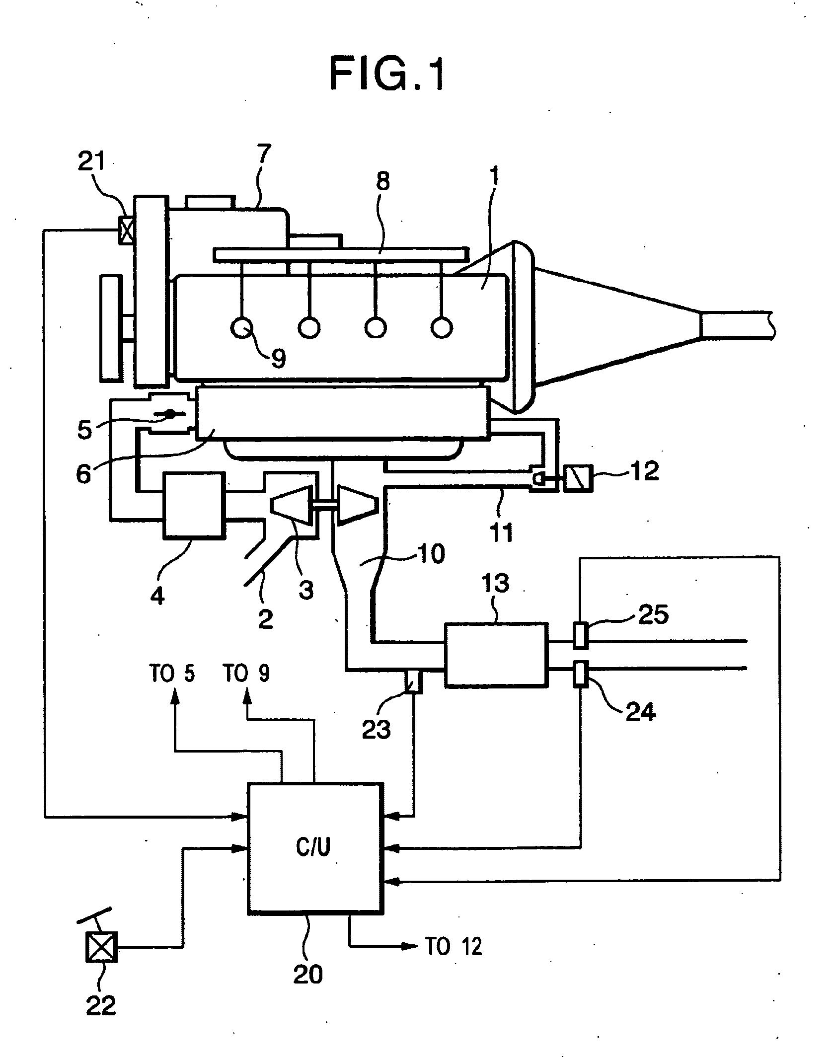
[0023]FIG. 1 Is a system diagram of an internal combustion engine (a diesel engine herein) showing a first embodiment according to the present invention.

[0024] In a diesel engine 1, air sucked into an intake pipe 2 is supercharged by an intake compressor of a variable nozzle type turbocharger 3, cooled by an inter-cooler 4, then passes through an intake air throttle valve 5 and afterwards, flows into a combustion chamber of each cylinder via a collector 6. Fuel is pressured by a high pressure fuel pump 7 to be sent to a common rail 8, and is directly injected into the combustion chamber from a fuel injection valve 9 of each cylinder. The air flown into the combustion chamber and the fuel injected into the combustion chamber are combusted herein by compression ignition, and an exhaust gas flows out into an exhaust passage 10.

[0025] A part of the exhaust gas flown out into the exhaust passage 10 is recirculated to an intake side via an EGR control valve 12 through an EGR pipe 11. The...

second embodiment

[0063] Next, a second embodiment according to the invention will be explained.

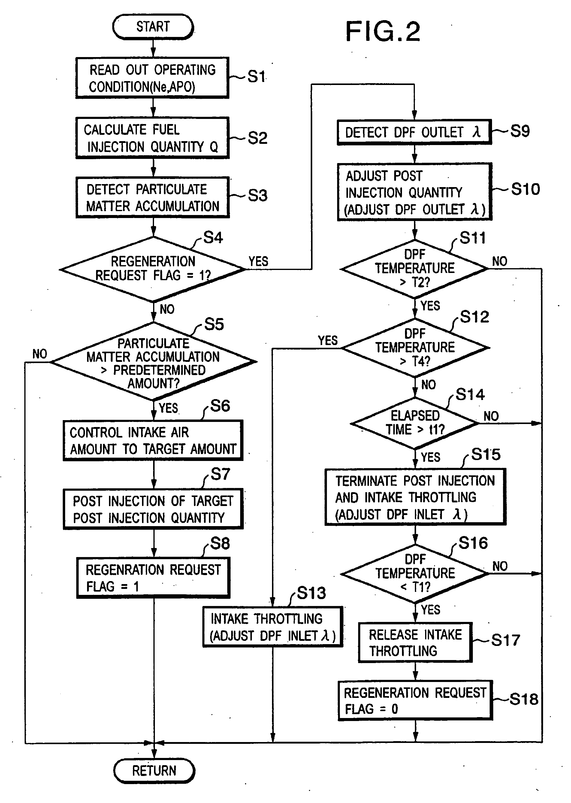
[0064] In the first embodiment, the exhaust gas air-fuel ratio at the outlet of the DPF 13 is controlled to the stoichiometric ratio by the control of the post injection and / or the amount thereof. In the second embodiment, the exhaust gas air-fuel ratio at the outlet of the DPF13 is controlled to the stoichiometric ratio, by controlling an EGR rate by an opening angle control of an EGR control valve 12.

[0065]FIG. 8 is a flowchart of a DPF regeneration control in the second embodiment. This flowchart is different only in S7 and S10 from the first embodiment (FIG. 2), which only will be explained.

[0066] At S7, a target EGR rate corresponding to the current operating condition (engine rotation speed Ne and fuel injection quantity 0) is determined from a target EGR rate map shown in FIG. 9, and the opening angle of EGR control valve 12 is controlled so as to obtain the determined target EGR rate. The target ...

third embodiment

[0069] Next, a third embodiment according to the invention will be explained.

[0070]FIG. 10 is a system diagram of a diesel engine showing the third embodiment according to the present invention, a different point of the second embodiment from the first embodiment is that an NOx trap catalyst 14 is disposed on the downstream side of the DPF 13 with the three-way function on the exhaust passage 10, which traps Nx when the air-fuel ratio of the exhaust gas flowing thereto is lean, and when i is the stoichiometric ratio or rich, eliminates and purifies NOx.

[0071]FIG. 11 is a flowchart of a DPF regeneration control in the third embodiment. This flowchart is different only in S6, S11, S12, and S16 from the first embodiment (FIG.), which will be explained.

[0072] At S6, the intake air amount is adjusted by controlling the intake air throttle valve 5 to start the regeneration of the DPF 13. In order to promote the temperature rise of the DPF 13, the intake air amount is made large so that ...


PUM

PropertyMeasurementUnit
temperature T2aaaaaaaaaa
concentrationaaaaaaaaaa
temperatureaaaaaaaaaa

Abstract

According to the present invention, there is disposed in an exhaust passage of an internal combustion engine a filter that traps particulate matter In an exhaust gas, and a catalyst with a three-way function is carried on the filter. At the filter regeneration, by controlling such as an injection amount of post injection, an air-fuel ratio of the exhaust gas at an outlet of the filter is controlled to a stoichiometric ratio, and also by controlling such as an intake air throttle valve, an oxygen concentration of the exhaust gas at an inlet of the filter is controlled. Hence, at the filter regeneration, the particulate can be reliably burned and removed, and at the same time, NOx in addition to HC and CO can be purified.

Description

TECHNICAL FIELD [0001] The present invention relates to an exhaust gas purification apparatus for an internal combustion engine and a method thereof, and particularly to a regeneration treatment technology of a filter that traps particulate matter being fine grains in an exhaust gas. BACKGROUND ART [0002] Heretofore, when a filter that traps particulate matter in an exhaust gas is located at an exhaust passage as an exhaust gas purification apparatus, regeneration treatment of the filter is required (treatment to burn and remove the particulate matter trapped in the filter). [0003] Japanese Patent No. 2858184 includes a heating unit that heats particulate matter to an initial temperature of a filter and a particulate trapping amount of the filter, a gas supply unit that supplies a gas including an oxygen for promoting the burning of heated particulate matter, a filter temperature detection unit that detects a side temperature of the filter, and a control unit that controls an operat...

Claims


Application Information

Patent Timeline
Patent Type & Authority Applications(United States)
IPC IPC(8): B01D46/42B01D46/44B01D53/94F01N3/02F01N3/023F02M25/07F01N3/035F01N3/08F01N3/20F01N3/24F01N3/28F01N9/00F02B29/04F02B37/00F02B37/24F02D21/08F02D41/00F02D41/02F02D41/14F02D41/40
CPCF01N3/023Y02T10/22F01N3/0814F01N3/0821F01N3/0842F01N9/002F01N2250/02F01N2250/12F01N2250/14F01N2430/085F01N2570/04F01N2570/10F01N2570/12F01N2570/14F02B29/04F02B37/00F02B37/24F02D41/0002F02D41/0055F02D41/0245F02D41/029F02D41/1439F02D41/1441F02D41/405F02D2200/0802F02D2200/0812F02M25/0707Y02T10/44Y02T10/26Y02T10/47F01N3/035F02M26/05Y02A50/20Y02T10/12Y02T10/40F01N9/00
Inventor KITAHARA, YASUHISA
Owner NISSAN MOTOR CO LTD
Why Eureka
Try Eureka