Method and apparatus for determining and assessing a characteristic of a material

a technology of characteristics and methods, applied in the direction of instruments, specific gravity measurement, heat measurement, etc., can solve the problems of nde techniques, failure to evaluate or otherwise assess the performance effects of identified potential flaws, cracks, anomalies, etc., and achieve the effect of low cost and high accuracy

Inactive Publication Date: 2005-04-07
LUNA INNOVATIONS
View PDF20 Cites 87 Cited by
  • Summary
  • Abstract
  • Description
  • Claims
  • Application Information

AI Technical Summary

Benefits of technology

These and other drawbacks with prior NDE equipment and NDE approaches are overcome with an acoustic energy-based, differential, non-contact (or contact) testing approach that provides low cost, highly accurate, and reliable information to (a) identify flaws and anomalies and (b) assess the integrity of a particular material. This approach is not hindered by surface conditions or impediments, and indeed, looks beneath the surface of the material by propagating and detecting an acoustic wave through the material using differential sensors. A dynamic differential measurement is made of the material under a load condition and an unloaded condition that allows identification and assessment of various characteristics of the material. Multiple “windows” of information may be generated that permit (a) direct detection of flaws, defects, and anomalies using a scattering technique, (b) detection of crack closure and opening used to assess the stability of the material, (c) determination of strain on the material which relates to its performance, and (d) determination of defect dynamics linked to the defect size and stability.

Problems solved by technology

Moreover, NDE techniques traditionally identify certain flaws or defects, but do not evaluate or otherwise assess performance effects of identified potential flaws, cracks, or anomalies.
Nor do they provide a mechanism for documenting a history and assessing the performance integrity of the material under test over time.
Some current NDE approaches utilize ultrasonic techniques, but these ultrasonic techniques typically require context scanning of the material under test.
Drawbacks with thermal imaging include the need for flash-heating the test material, often requiring coating the test material, and also the need for expensive and sophisticated thermal imaging and processing equipment.
Thermographic techniques are also not particularly effective with respect to detecting deep, subsurface flaws or relatively small surface flaws.
Radiographic NDE techniques typically radiate the material using X-rays, but the accuracy of radiographic techniques is generally less than satisfactory for small defects, and the radiation source poses a health / safety risk.
Nevertheless, there are thousands of rail incidents per year, some costing millions of dollars.
And although these NDE techniques may be workable in a laboratory environment or for small amounts of material to be tested, they are less practical when it comes to testing materials in the field or large quantities of material, e.g., miles of railway tracks, piping, etc.
NDE performance may also be adversely effected by dirt, grease, corrosion, chemical reactions, etc. on the surface layer of the material to be tested.

Method used


Image

  • Method and apparatus for determining and assessing a characteristic of a material
  • Method and apparatus for determining and assessing a characteristic of a material
  • Method and apparatus for determining and assessing a characteristic of a material

Examples


Embodiment Construction

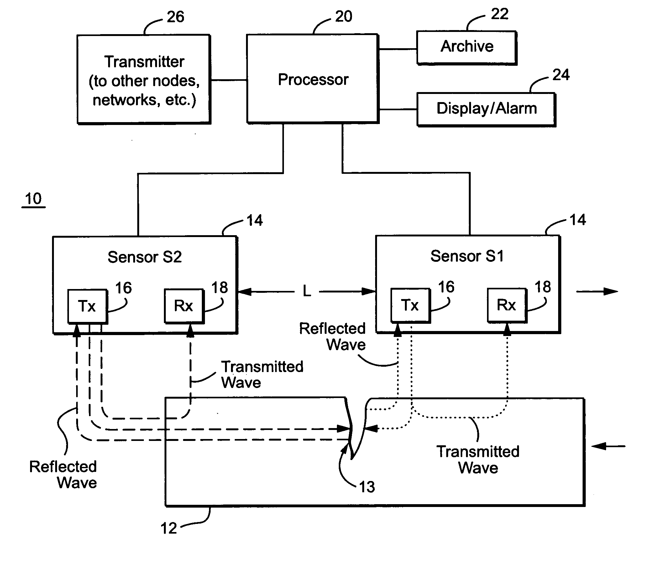
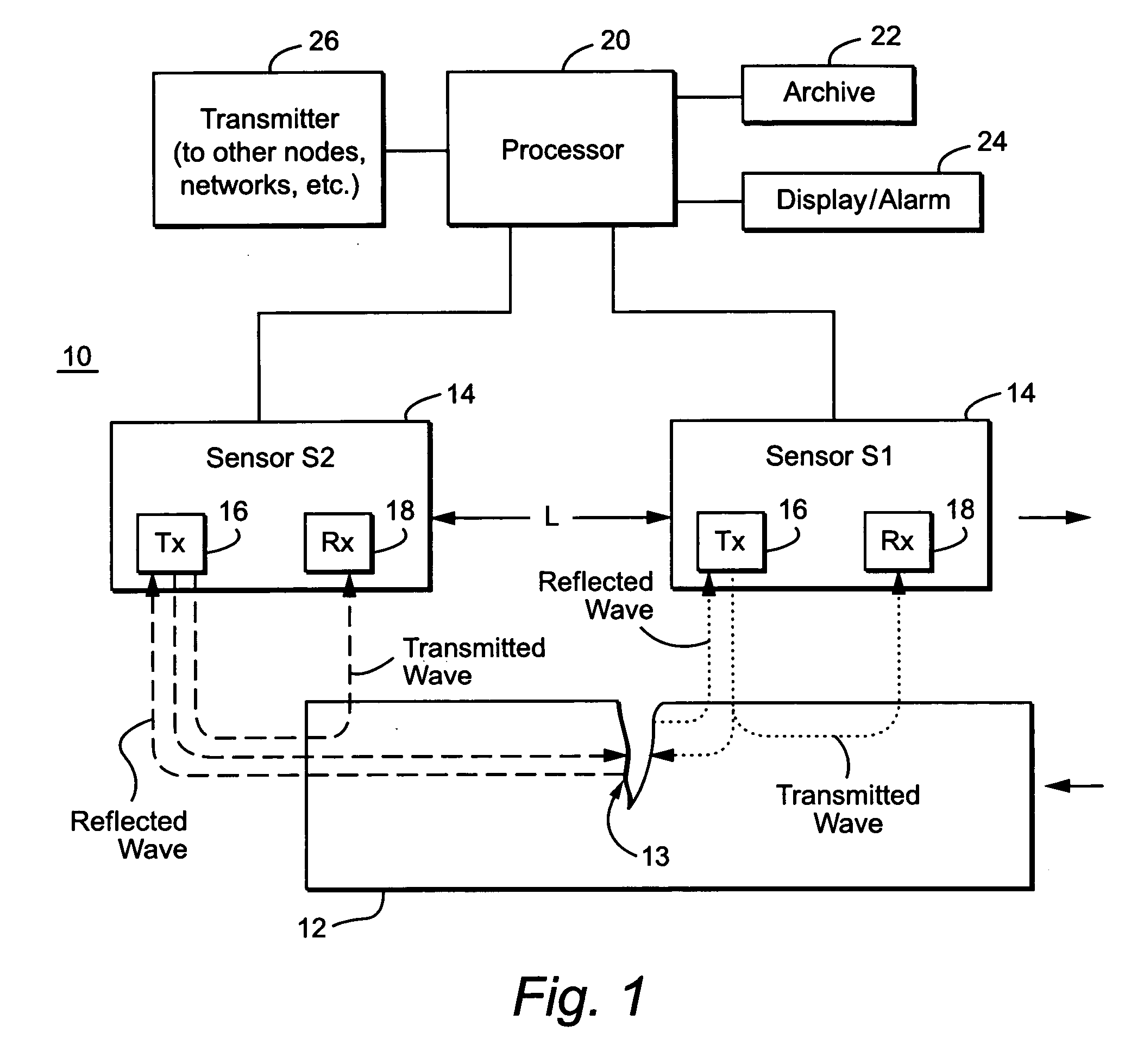
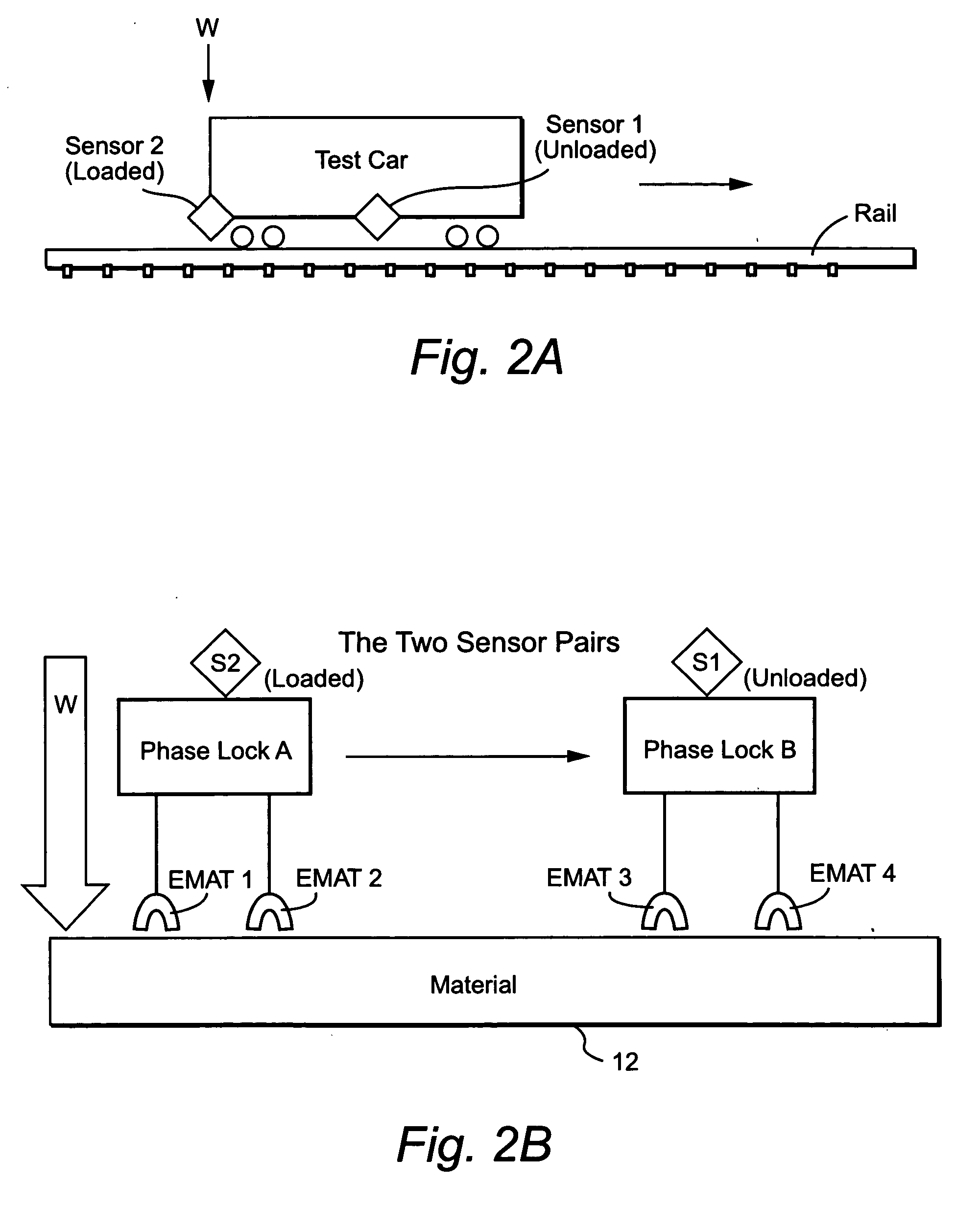
The following description sets forth specific details, such as particular embodiments, procedures, techniques, etc. for purposes of explanation and not limitation. But it will be appreciated by one skilled in the art that other embodiments may be employed apart from these specific details. For example, although the following description is facilitated using a non-limiting example application to rail inspection, the present invention may be employed to inspect and assess any solid, liquid, or gas material in which an acoustic wave can propagate. In some instances, detailed descriptions of well known methods, interfaces, circuits, and device are omitted so as not obscure the description with unnecessary detail. Moreover, individual blocks are shown in some of the figures. Those skilled in the art will appreciate that the functions of those blocks may be implemented using individual hardware circuits, using software programs and data, in conjunction with a suitably programmed digital ...


PUM

PropertyMeasurementUnit
frequencyaaaaaaaaaa
velocityaaaaaaaaaa
stressaaaaaaaaaa

Abstract

An acoustic energy-based, non-contact or contact testing approach provides low cost, highly accurate, and reliable information to (a) identify flaws and anomalies and (b) assess the integrity of a particular material. This approach is not hindered by surface conditions or impediments, and indeed, looks beneath the surface of the material by propagating an acoustic wave through the material using two differential transducers. A dynamic differential measurement is made of the material under a load condition and an unloaded condition that allows identification and assessment of various characteristics of the material. Multiple “windows” of information may be generated that permit (a) direct detection of flaws, defects, and anomalies using a scattering technique, (b) detection of crack closure and opening used to assess the stability of the material, (c) determination of strain on the material which relates to its performance, and (d) determination of defect dynamics linked to the defect size and stability.

Description

FIELD OF THE INVENTION The present invention relates to a method and apparatus for determining characteristics of a material. One non-limiting and example application is inspection of rails in a railway system to detect flaws, cracks, or other changes in the rail that may impact the safety or performance of the railway system. There are many other related and unrelated applications. BACKGROUND Non-Destructive Evaluation (NDE) equipment is used to detect the presence of certain flaws, such as cracks, in various structures such as rails, airplanes, automobiles, nuclear reactor systems, pipes, etc. While most NDE equipment aims to detect the presence of such cracks, flaws, or anomalies, etc. at the surface of a structure, it is desirable to also detect their presence beneath the structure surface to more reliably identify portions of the structure at risk and to prevent failure of the structure with potentially catastrophic results. Moreover, NDE techniques traditionally identify cer...

Claims


Application Information

Patent Timeline
Patent Type & Authority Applications(United States)
IPC IPC(8): G01BG01N3/00G01N3/32G01N29/00G01N29/02G01N29/04G01N29/07G01N29/11G01N29/22G01N29/30
CPCG01N29/07G01N29/11G01N29/227G01N29/30G01N2203/0016G01N2203/0023G01N2291/2623G01N2203/0075G01N2291/02491G01N2291/02827G01N2291/02881G01N2291/044G01N2291/048G01N2203/0062
Inventor HEYMAN, JOSEPH S.LYNCH, JOHN T.
Owner LUNA INNOVATIONS
Why Eureka
Try Eureka