
Method for driving multiple-module mechanisms by a single motor and redundant modular robots produced therefrom

a technology of multiple modules and robots, applied in the direction of mechanical control devices, process and machine control, instruments, etc., can solve the problems of complex control system for all motors, inability to operate correctly, complex mechanical complexity of robots, etc., and achieves simple and economical manufacturing and maintenance, easy assembly and disassembly, and high payload capacity.

Inactive Publication Date: 2005-04-07
ANANIEV ANANI +3
View PDF9 Cites 11 Cited by
  • Summary
  • Abstract
  • Description
  • Claims
  • Application Information

AI Technical Summary

Benefits of technology

[0038] One advantage of the present invention is that it provides a method for driving multiple-module mechanisms by a single irreversible motor and redundant modular robots produced therefrom, whereby the limitations as encountered by the prior art can be overcome. This method can be used in a variety of mechanical constructions where modularity and simplicity are aimed.
[0039] Other advantage of the present invention is that it provides a method for driving mechanisms assembled from multiple modules of the same type and redundant modular robots produced therefrom such that the modules of which are either identically repetitive or with some dimensional modifications, each module itself being constructed of repetitive elements.
[0040] Another advantage is that it provides redundant modular robots, the construction of which can be expanded and reconfigured according to the type of task to be accomplished.
[0041] Still another advantage is that it provides redundant modular robots, which use low variety of components that are easy to assemble and disassemble that makes the robots relatively simple and economical to manufacture and maintain.
[0042] Further advantage is that it provides redundant modular robots with relatively lightweight structure that has potentially higher payload capacity.
[0043] Still further advantage is that it provides redundant modular robots with simplified control system for independent control of all robot modules employing dominantly on-off logic control actions to the electromagnetic clutches and breaks and simple single-axis motor regulator.

Problems solved by technology

Normally, robots have mechanical complexity and high cost.
Moreover, they are not redundant and are therefore incapable of functioning correctly in case of more complicated robot configurations or motions.
Diverse modifications of this concept are known, but all they possess various types of deficiencies such as partial or total breakdown of the robot in the case of cable breakage, non-controllable robot in case of failure of a transmission, limited or very limited working space, need of plurality of driving motors associated with respective degrees of freedom, which requires also very complicated control system for all motors.
A second prior art technique referred as multiple rotation robot mechanism is known that avoids the use of cables (wire ropes) but involves a lot of driving motors, which result in higher own robot weight and complex control system.
A third prior art technique referred as deformation in a plane is known that also avoids the limitations involved by using the cables (wire ropes) but also employs relatively high number of driving motors, which give higher robot weight and complex control system.
All pointed prior art techniques have the disadvantage of using large number of motors with respective multi-axes control system, the complexity of which is increased due to the need of synchronous operation of different subsets of motors.
Hence, the existing solutions so far accommodate limitations both in terms of complexity and costs.
As the produced mechanical energy cannot be easily stored for future use, it must be utilized directly after being delivered to the said multiple-module mechanisms of the said modular robot.

Method used


Image

  • Method for driving multiple-module mechanisms by a single motor and redundant modular robots produced therefrom
  • Method for driving multiple-module mechanisms by a single motor and redundant modular robots produced therefrom
  • Method for driving multiple-module mechanisms by a single motor and redundant modular robots produced therefrom

Examples


first embodiment

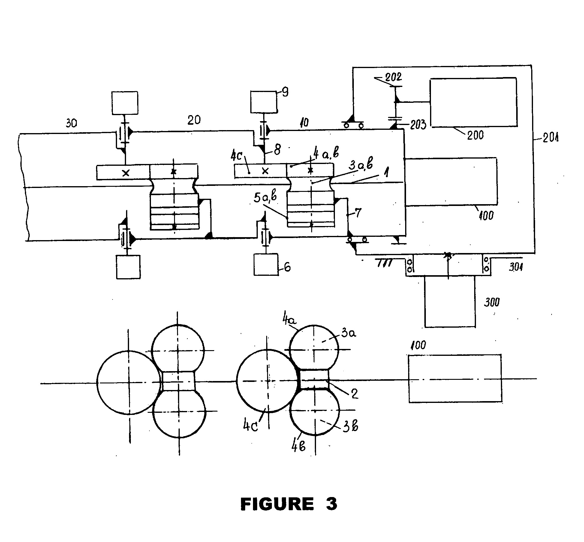
[0057] As the kinematical scheme and principle of operation of the first embodiment mechanism can be designed in a variety of concrete mechanical constructions, they are considered as not deviating from the spirit of the present invention and therefore embraced by it.

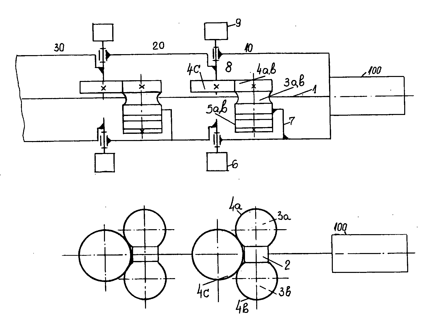
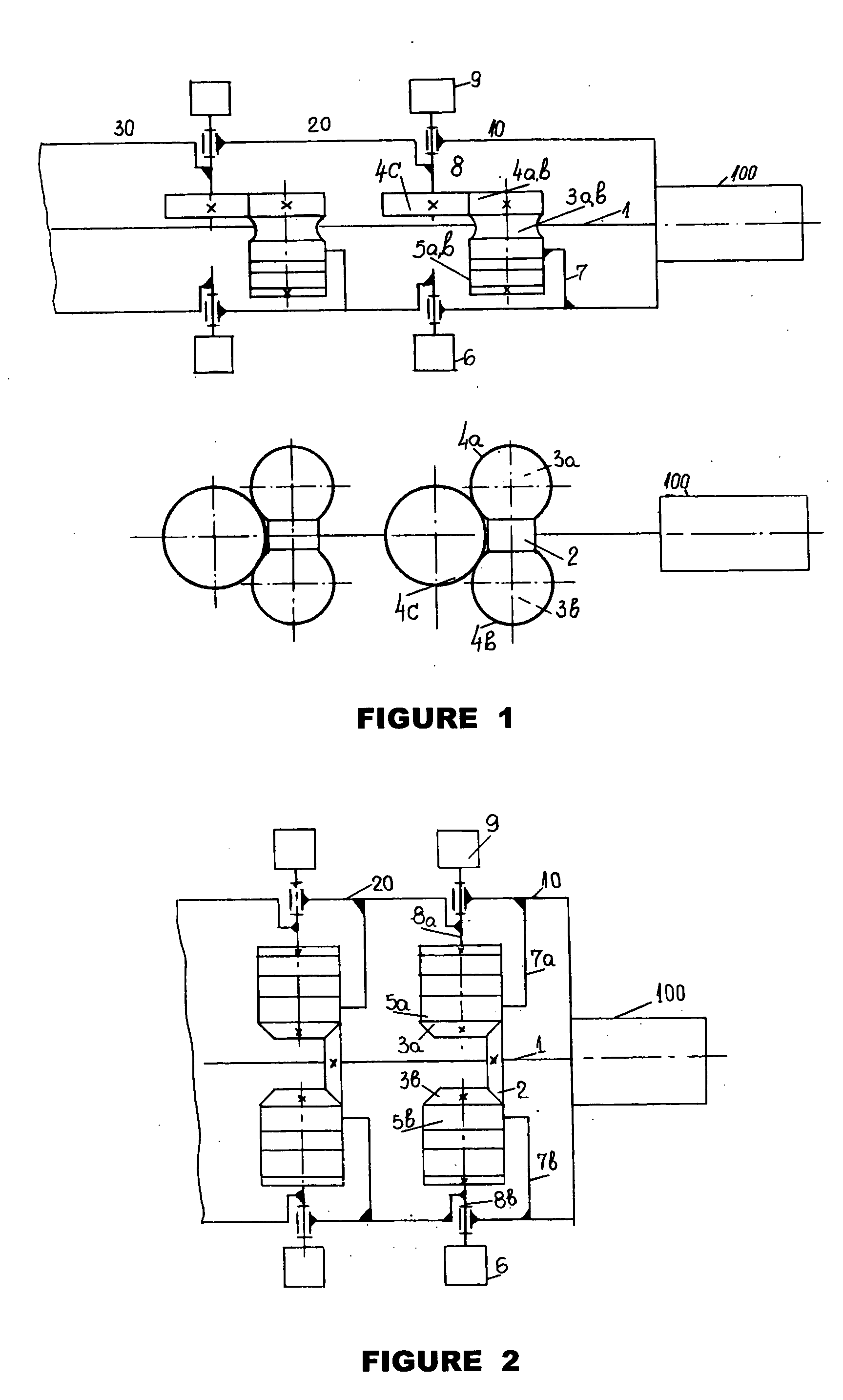
[0058] A second embodiment of the redundant modular robot of the invention is illustrated on FIG. 2. For convenience of the explanation and easy comparisons of the schemes all participating components have the same indices. The main difference between the first and second preferred embodiment is in the way of implementing the internal mechanism of the multiple modules. Therefore the general structure of the redundant modular robot is the same as in the first embodiment. It is presented here for keeping the completeness of the description.

[0059] The redundant modular robot has a plurality of connected to each other modules 10, 20, 30, etc. driven by a flexible shaft 1. Each of the modules 10, 20, 30, etc., has the same ...

second embodiment

[0061] The particular implementation of each module 10, 20, 30, etc., in this second embodiment is further disclosed by the description of the internal mechanism of these modules. Referring again to FIG. 2, a driving wheel 2 is fixed to the said flexible shaft 1 and transfers the rotation from the driving motor 100 to the mechanism of said module. A pair of transferring wheels 3a and 3b coupled to both sides of the driving wheel 2 such that transferring wheel 3b rotates at opposite direction to the 3a wheel. These driving wheels 3a and 3b rotate permanently as the driving motor 100 and the flexible shaft 1 do.

[0062] Pair of electromagnetic clutches 5a and 5b is provided for switching one of the opposite directions of rotations further to the mechanism. The body of the clutches 5a and 5b are fastened to the body of said module through fixtures 7a and 7b. The shaft of clutch 5a is fixed to the transferring wheel 3a and the shaft of clutch 5b is fixed to the transferring wheel 3b. When...


PUM


Abstract

A method for driving multiple-module mechanisms by a single motor and redundant modular robots produced therefrom comprises a flexible shaft, which transports the rotation from only one irreversible motor to the mechanisms inside all multiple modules of the robot by means of a plurality of pairs of electromagnetic clutches and respective kits of transmission and driving wheels to distribute selectively the torque / rotation of the motor independently to anyone of the robot modules, electromagnetic breaks keep the desired pose of the robot. A simple control system regulates the speed of the motor and employs simple on-off logic control of the electromagnetic clutches and breaks based on feedback of a set of sensors measuring the angle between each two consecutive robot modules. The versatile kinematics provides the possibility the same construction to be used for implementing a manipulator arm, “elephant trunk”, “snake” or “earthworm”.

Description

BACKGROUND OF THE INVENTION [0001] 1. Field of the Invention [0002] The present invention relates to a method for driving mechanisms assembled from multiple modules of the same type and various constructions of redundant modular robots produced therefrom, which are suited for various tasks in places that are not easily accessible to operators and mobile rescue machine. [0003] 2. Description of the Prior Art [0004] In this description, the conventional vocabulary used in the technical field of robotics will be used in general. By “robot” is meant an articulated mechanical system constituted by a connection of at least two modules, with which is associated a control unit. [0005] By the term “end-effector” is meant any system, active or passive, allocated normally at the distal end of the robot construction, adapted to the application envisaged, for example a gripper, a point, a tool, etc. [0006] By the term “position” is meant a position and / or an orientation in space, of the end-effe...

Claims


Application Information

Patent Timeline
IPC IPC(8): B25J9/06B25J9/10B25J17/02
CPCB08B9/045B25J9/06Y10T74/20305B25J9/102B25J17/025B25J9/065
Inventor ANANIEV, ANANIPETROV, EVGENIYHADJIYSKI, BANKOKALAIKOV, IVAN
Owner ANANIEV ANANI
Learn More