Beverage dispensing apparatus

a beverage and apparatus technology, applied in the direction of liquid transfer devices, packaging goods, transportation and packaging, etc., can solve the problems of excessive foam, unsatisfactory consumer and beverage vendor, and a tendency to form foam, etc., to achieve low manufacturing and maintenance costs.

Inactive Publication Date: 2005-04-07
LAMINAR TECH
View PDF35 Cites 14 Cited by
  • Summary
  • Abstract
  • Description
  • Claims
  • Application Information

AI Technical Summary

Benefits of technology

[0012] The present invention is directed to a beverage dispensing device for dispensing pressurized beverages at a flow rate substantially higher than prior mechanical tap apparatus without producing excessive foaming. It can be implemented as a purely mechanical device so as to keep manufacturing and maintenance costs low. In addition, the present invention can be implemented without the use of reservoirs at or near the point of dispensing, thus facilitating cleaning and retrofitting to existing bar tops.

Problems solved by technology

Due to the complex chemical makeup of beer, foam tends to form when this dissolved CO2 comes out of solution.
One cause of such foaming is simply the pressure differential between CO2 dissolved in the beer and CO2 present in the ambient atmosphere; CO2 will naturally be released from the beer when the beer is exposed to the atmosphere.
Another cause of such foaming is the turbulent nature by which beer is dispensed from conventional faucets; even when dispensed carefully, beer splashes onto the walls and bottom of the container and foam results.
On the other hand, too much foam is undesirable to the consumer and the beverage vendor.
Since foam fills up a container with CO2 instead of with liquid beer, excessive amounts of foam leave the consumer dissatisfied, often to the point of requesting a new container be served.
They can partially fill a container, wait for the foam to dissipate and then add additional beer, a time-consuming process.
Alternatively, they can pour out excess foam as they are filling the container, wasting beer in the process.
One drawback with these systems is that they typically employ elaborate electronic control mechanisms, making them expensive to manufacture and maintain.
Additionally, some of these systems employ the use of a reservoir near the point of the faucet making the devices large and difficult to clean.
Moreover, the retrofit of such devices onto existing bar tops can be difficult and expensive.

Method used


Image

  • Beverage dispensing apparatus
  • Beverage dispensing apparatus
  • Beverage dispensing apparatus

Examples


Embodiment Construction

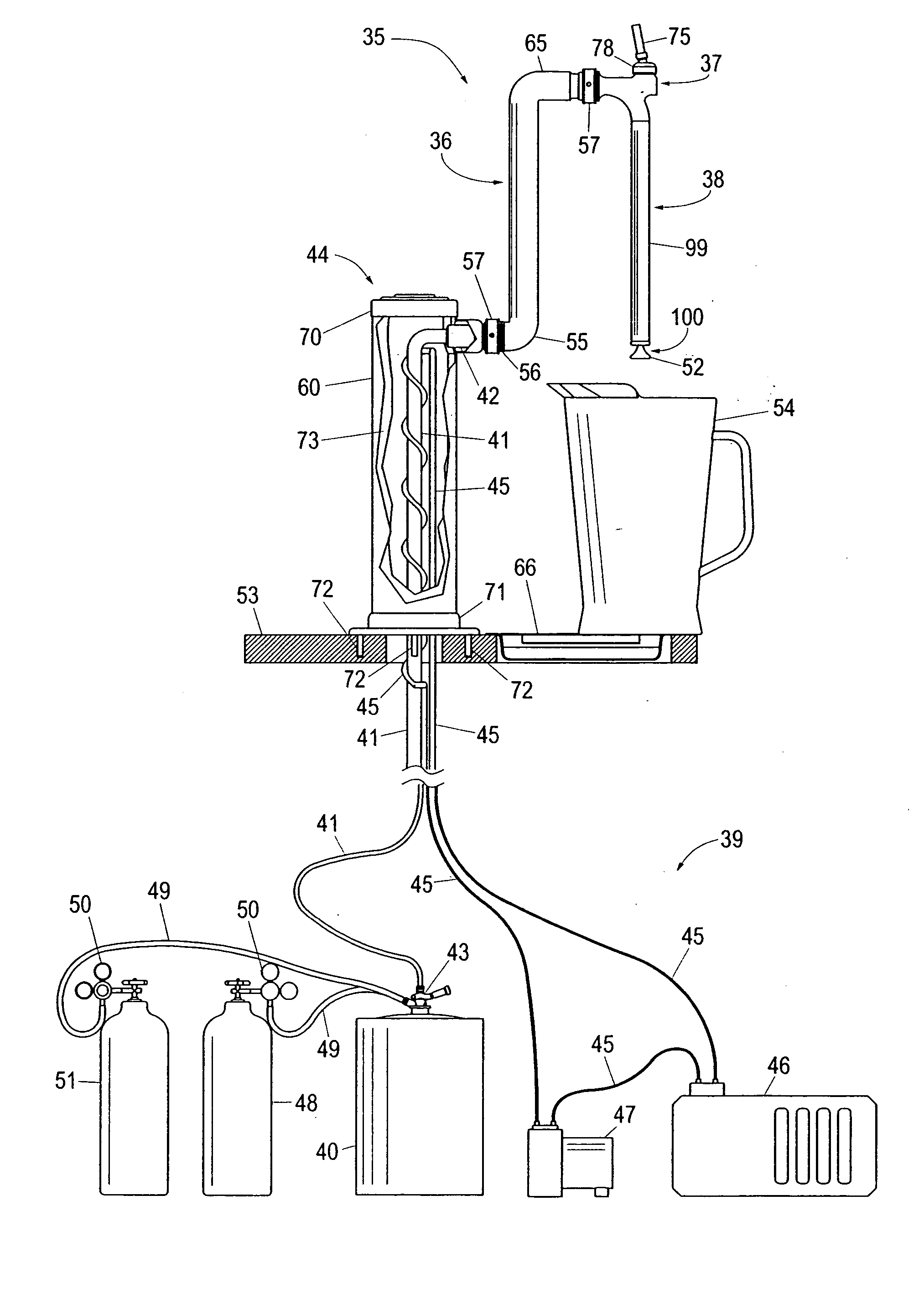
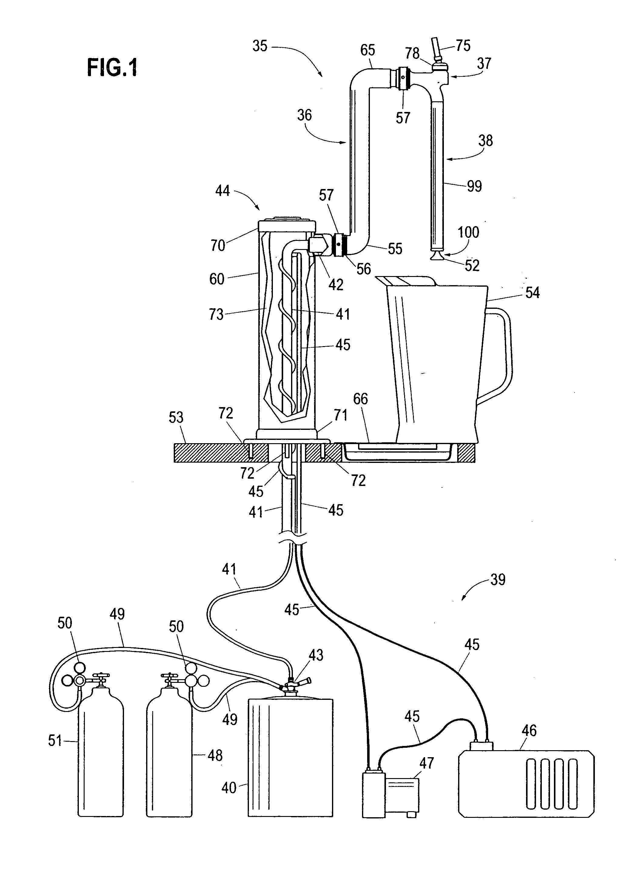
[0048] As shown in FIG. 1, the rapid beverage dispensing device 35 comprises a neck assembly 36, a valve assembly 37, and a downward-extending nozzle assembly 38. In a preferred embodiment, neck assembly 36 is substantially vertical. The rapid beverage dispensing device 35 is designed to attach to a conventional pressurized beverage dispensing system, such as a beer dispensing system 39 that includes a beer keg 40 or similar beverage-containing reservoir and beverage tubing 41 for conveying a beverage from a container or beer keg 40 to the rapid beverage dispensing device 35. A shank 42 connects the rapid beverage dispensing device 35 to beverage tubing 41. Keg tapping device 43 connects beverage tubing 41 to beer keg 40. Draft dispensing tower 44 supports shank 42.

[0049] Beer produced by most major manufacturers in the United States is formulated to be stored and served optimally at approximately 38 degrees Fahrenheit (3.3 degrees Celsius). If the beer is warmer than this optimal ...


PUM

PropertyMeasurementUnit
temperatureaaaaaaaaaa

Abstract

A beverage dispensing device for dispensing pressurized beverages at a high flow rate without producing excessive foaming comprising a streamlined valve assembly and a downward extending nozzle assembly which permits a range of containers to be filled from the bottom.

Description

CROSS REFERENCE TO RELATED APPLICATION [0001] This application is a divisional of U.S. patent application Ser. No. 10 / 388,907, entitled “Beverage Dispensing Apparatus,” filed on Mar. 13, 2003, the contents of which are incorporated herein by reference.BACKGROUND OF THE INVENTION [0002] The present invention relates to an apparatus for dispensing carbonated or pressurized beverages, and more specifically to an apparatus for dispensing carbonated or pressurized beverages at high flow rates with minimal foaming. [0003] Pressurized beverages, such as beer, are produced in a manner that the beverage contains a certain amount of dissolved gas, typically carbon dioxide (CO2). While a certain amount of dissolved CO2 occurs naturally in the beer brewing and fermentation process, most large commercial breweries dissolve additional CO2 into their product. Adding additional CO2 serves two main purposes for the commercial breweries. First, from a quality control standpoint, all the beer produced...

Claims


Application Information

Patent Timeline
Patent Type & Authority Applications(United States)
IPC IPC(8): B05B1/02B05B1/26B05B1/30B67D1/00B67D1/08B67D1/14B67D7/42F16K1/12
CPCB05B1/265B05B1/3013B67D1/0865B67D1/0872B67D1/127F16K1/12B67D1/1422B67D1/1455B67D1/1466B67D2210/00052B67D1/14
Inventor YOUNKLE, MATTHEW C.
Owner LAMINAR TECH
Why Eureka
Try Eureka